1. Introduction
Green development is an international trend. At present, environmental and resource problems have become the common challenges of mankind, and consensus has been reached on how to achieve sustainable development. Green manufacturing is undoubtedly the only way to industrial upgrading and transformation. The “Made in China 2025” initiative has identified green manufacturing as one of the five key construction projects and organized the implementation of special technological upgrading projects to improve energy efficiency, clean production, water and pollution control, and recycling in traditional manufacturing industries. The development of green manufacturing technology is beneficial to alleviating the current environmental resource constraint problem and will help foster new economic growth points quickly. Moreover, it is of far-reaching historical meaning to accelerating the transformation of economic development mode, promoting industrial transformation, upgrading and transforming old and new driving forces, and enhancing the international competitiveness of the manufacturing industry.
With the continuous development of the automobile industry, world car sales records have been set many times. Research shows the auto industry has undergone start-up, and after rapid growth and prosperity, officially entered the mature stage, and the market size has reached a stable stage [
1]. However, with the rapid development of the automobile industry, a large amount of mineral oil cutting fluid is used in the conventional production line of automobile wheel hub processing, resulting in resource waste, environmental pollution, harm to workers’ health, and other problems [
2]. According to the investigation of a small- and medium-sized automobile wheel hub manufacturer, the annual consumption of lubricant is up to 650,000 tons. Used for lubricating fluid procurement, waste liquid treatment and other aspects of the cost of reach 3 million yuan, cause the working environment to be dirty, disorderly, and poor, and lead to other problems. Therefore, while transforming the production line to achieve automation, the clean production of automobile wheel hub must be ensured, so that the perfect combination of clean production and automatic production is the only way to future production.
With the international support for green manufacturing, green cooling and lubrication methods have also been developed. Professor F. Klocke [
3] of the Aachen University of Technology in Germany proposed “dry cutting,” which was the earliest green processing technology applied in the automobile industry. Dry cutting ensures the tool life and precision of parts and does not use lubricant in the processing [
4,
5,
6,
7]. The successful application of dry processing in mechanical processing has brought a new way for green processing. After that, many researchers have performed experimental research on dry processing for materials such as cast iron, aluminum, and aluminum alloy [
8]. A variety of basic machining forms are also studied; the results show dry machining improves the environmental protection of the processing and avoids the harm of cutting fluid to workers’ bodies [
9]. However, due to the lack of direct lubrication of the cutting fluid, to achieve the processing quality of pouring lubrication and ensure the toughness, hardness, and wear resistance of the tool, the dry processing is limited by the tool; because no media are involved in the processing, chip removal and heat exchange performance is insufficient, inevitably resulting in workpiece surface burns [
10,
11]. With the in-depth research of scholars, Yokogawa and Kazuhiko [
12,
13] of Meiji University in Japan and other scholars proposed low temperature cooling technology. Low temperature cooling technology is to spray a low-temperature gas medium to the cutting area to cool the cutting area to meet the processing requirements. Some scholars [
14,
15,
16,
17] have studied the cryogenic gas medium and suggested argon, carbon dioxide, nitrogen, and other gases can be used as machining cooling medium [
18,
19,
20]. Many experiments have explored the effect of cryogenic cooling technology in turning, milling, and other processing forms [
21,
22,
23,
24]. The results show the workpiece quality, tool life, and lubrication performance obtained by low-temperature cooling and lubrication are better than those achieved by dry cutting; but compared with pouring lubrication, the cost is almost the same [
25]. In addition, liquid nitrogen, carbon dioxide, and other cooling media not only cost much in storage and transportation [
26,
27] but also lead to the reduction of oxygen content in the processing and cause suffocation of workers, which conflicts with green development and human health and needs further development and research. The improvement of the tool has also been studied by many scholars, through tool material mixing and research, to produce high-quality tools and better ensure the processing quality [
28]. After dry cutting, a minimum quantity lubrication (MQL) technology between pouring cutting and dry cutting is proposed to ensure the machining quality by using cutting fluid at the minimum [
29]. MQL technology is to add minimum quantity lubricating oil in high-pressure gas; with the help of high-pressure airflow, the minimum quantity lubricating oil atomizes into the high-speed cutting area, for cooling lubrication and chip discharge [
30]. MQL uses vegetable oil with excellent biodegradability as the base oil, which greatly improves the working environment, reduces the pollution to the environment, and ensures the quality of the workpiece processing [
31,
32,
33]. In the development of MQL technology, plant lubricants are mixed, and their lubrication properties are studied through different proportions [
34]. Multienergy field coupling research was carried out by adding electrostatic field [
35,
36], cold air field [
37,
38,
39], and other energy fields to MQL [
40,
41,
42] to improve the cooling lubrication effect. Nanofluids were added based on the minimum quantity of lubrication oil to improve the heat transfer capacity of lubricating oil and the lubrication effect [
43,
44,
45,
46,
47]. Therefore, the integration of trace lubrication into the production line has become an inevitable choice.
However, the conventional production line has the problem of insufficient automation that limits the improvement of lubrication conditions and prevents the synchronization of trace lubrication and production factors, so the overall production line needs to be improved. With the growth of automobile sales, the production efficiency of the wheel hub has been further required, and it is an inevitable choice to enhance the intelligent production line. The wheel hub is an important part of the car, and its precision roundness and coaxiality remarkably influence car service life, driving stability, and driver safety [
48]. As a result, the intelligent transformation of production line needs not only to improve production efficiency but also to ensure the quality of wheel hub production. However, wheel manufacturers vary in scale, hub machining is still mostly artificial with machine tool processing to complete the production, and a large amount of manpower is used, resulting in a low degree of production line automation and unstable product performance, greatly restricting the development of the wheel industry [
49]. Some manufacturers try to adopt intelligent automatic production line transformation, but enterprises lack their own core technology and intelligent production line cost is high, so manufacturers are unable to update the equipment.
Facing the needs of wheel hub production, a flexible machining production line for automobile wheel hub must be set up. The flexible automatic production line of automobile wheel hub processing needs to realize multispecification, multisize, and variable batch wheel hub production, and meet the automatic flow operation of wheel hub loading and unloading, rough machining, semifinishing, finishing, and drilling [
50]. Many scholars have studied wheel hub processing due to its diversity [
51]. Conventional hub processing needs to replace different tooling equipment to complete the processing of different types of hub, which reduces the production efficiency and increases the cost. Facing the production mode of multisize and multispecification hub, automated flexible hub production and processing has become the general trend. Zheng Wei [
52,
53] designed and analyzed the flexible fixture of the wheel hub. By driving the connecting rod with the rotating mechanism, the hub of different radii can be clamped, and the clamping force and positioning error of the fixture are analyzed. Hub identification and analysis in intelligent production line is also extremely important. Li Liangchen [
54] collected surF-LBP integration features of various types; a hub recognition system was established by pattern recognition and recognition algorithm to realize automatic identification of hub models and improve the intelligent level of hub production line. Zhao Haiwen [
55] and Zhu Chaoping [
56] improved the model through convolutional network and Faster-RCNN network to replace the manual detection of wheel hub surface defects and realize the online detection of wheel hub surface. Liang Yingfu [
57] designed the overall framework of the intelligent manufacturing system in automobile hub production line and combined MES system and PLC technology with a machine tool robot. Yin Cuntao [
58] used cloud computing, big data, Internet of things, and other technical means to build a hub automation manufacturing system to achieve remote control of automobile hubs. Hub automated flexible production line, from the fixture of flexible processing to the detection in the processing, and then to the combination of the whole production line and the Internet of things, the intelligent hub production line has been greatly developed.
Conventional production lines have the following technical difficulties: (1) A wide variety of wheel hub, different specifications, and sizes often need different processing equipment to complete the production. (2) The processing unit adopts the island layout, and the processing continuity between each unit is insufficient. (3) In the pouring lubrication condition, the splashing lubricant in the machining pollutes the environment and affects the health of workers. (4) The use of manual loading and unloading increases the cost and decreases the efficiency. Based on the above technical difficulties, intelligent, sustainable manufacturing production line for automobile wheel hub is designed. First, the machining of automotive wheel hubs is analyzed, the overall layout of the production line is designed, and each production unit achieves parallel production through the feeding device. Next, the process equipment system including the fixture and the MQL system are designed. The fixture achieved self-positioning and clamping functions through a linkage mechanism and a crank–slider mechanism, respectively, and the reliability of the mechanism is analyzed. The MQL system is installed on the machine tool. Finally, the trajectory planning of the robot with dual clamping stations is performed by RobotStodio.
2. Design of Production Line
Based on the production status of the automobile wheel hub, the automobile wheel hub production is analyzed and optimized, and the production line is designed based on the process planning.
2.1. Machining
The wheel hub has an approximately stepped shape with reinforcing ribs, and it can be classified as a disc cover type component [
59]. The processing technology of wheel hub unit is the most fundamental factor to ensure the quality of the wheel hub [
60]. The hub machining is divided into five processes, as shown in . According to the car hub’s need to carry out rough car, semifine car, and fine car processing, turning is divided into four processes, with drilling in the machining center as a process.
2.2. Overall Layout of Production Line
The conventional wheel hub processing production line, mostly manual handling material, not only reduces the production efficiency, but also increases the production cost. In addition, conventional wheel fixtures have insufficient positioning and clamping strokes and are not suitable for flexible machining of wheel hubs of various sizes. Based on the above technical difficulties, the layout of the wheel production line is optimized, the automatic feeding device and self-positioning wheel fixture are designed, and the MQL system is embedded.
Starting from the technological process, the loading and unloading device, machine tool fixtures, and MQL production conditions are designed as a whole, and the mechanism is shown in . By four vertical lathes and a machining center to complete the hub of five processes, five machine tools are arranged into a two-row layout, through ground track unloading manipulator to complete the machine and roller table, roller table, and roller table between the material transmission. MQL is embedded in each machine to improve the machining conditions. Five machine tools and three manipulators form a processing unit, and the workshop can arrange multiple processing units with unified feeding through the device.
. Structure diagram of clean production line for automobile wheel hub. 1. Material rack 2. First roller table$$\,$$3. Splitting device 4. Hub handling manipulator 5. Minimum quantity lubrication 6. Fixture 7. Machine tool 8. Discharging roller table$$\,$$9. Loading and unloading robot 10. Wheel hub 11. Hub positioning device.
3. Design Process Equipment System
Automobile wheel hub processing needs a loading and unloading system, a lubrication system, and a fixture lathe. The flexible design of fixture, MQL device, and loading and unloading manipulator are the necessary bases for the clean, flexible machining of the automobile wheel hub.
3.1. Flexible Design of Fixture
With the development of automobile industry, the wheel hub shows the characteristics of diversification, and the existing fixture flexibility degree is insufficient, resulting in the need for the replacement of fixture processing of different specifications of the wheel hub and seriously restricting the automation of hub production. To solve the above problems, the existing scholars [
61] used wheel clamp for the flexible design and analysis, but closely with line contact is not enough. To meet the needs of automatic production line, an automatic hub fixture is designed. shows the wheel hub fixture includes a fixture body and positioning device, the fixture body includes a fixed platform, numerous clamping claws are arranged in circumferential intervals along the fixed platform, and the clamping claws are used to clamp the outer rim of the wheel hub; numerous clamping claws are connected to the drive through the linkage mechanism, under the action of the drive, to make the claw radial movement along the fixed platform; the positioning device includes a movable platform that is slidingly connected to the claws, and the movable platform is mounted with a positioning module used to locate the inner rim or the outer rim of the wheel hub.
To solve the problem of repeated positioning accuracy, a self-positioning device is set to improve the positioning accuracy; to meet the multisize flexible machining of the hub, the clamping claw is tightened through the crank–slider mechanism, and the movable platform can be adjusted in the axial direction. The self-positioning device includes three positioning blocks, a connecting rod, a connecting frame, and the upper and lower parts of the rail frame. The clamping part comprises a fixed platform, a movable platform, and a clamping claw connected by a connecting rod mechanism.
The self-positioning device can realize the positioning before clamping, improve the positioning accuracy for clamping, and reduce the repeated positioning error. With the hub bottom plane as the main positioning datum, the movable platform limits the rotation of the X and Y axes and the movement of Z axes of the hub. Under the drive of the cylinder, the connecting rod mechanism drives the three positioning blocks to move outward at the same time, to limit the X and Y movement of the hub, and to realize the self-positioning of the hub. The fixed platform is connected to the machine tool. The movement of the clamping claw is controlled by the first cylinder, which converts the vertical driving force into horizontal radial force through a crank–slider mechanism. The clamping claw moves along the fixed platform radial under the action of radial force and carries on the radial clamping to the hub. The second cylinder drives the movable platform to move in the Z axis and coordinates the clamping claw to clamp the wheel hub in the axial direction.
. Structure diagram of fixture. 1. Fixed platform 2. Clamping claw 3. Movable platform 4. Self-positioning device.
In processing, fixture force should ensure not only undamaged workpiece but also normal processing [
62]. The minimum clamping force ensures the hub of automobile wheel is not deflected by the cutting force during machining. The cylinder should provide a minimum clamping force for the clamping claw to ensure the normal operation of processing. During processing, the position of the clamping claw and wheel hub is offset, and the friction force generated on the wheel hub is relative to the force couple to achieve static balance conditions:
The friction during clamping is generated by a single clamping force. The main cutting force generated by the tool’s contact with the hub acts on the hub, forming a couple of forces.
The parameters of the machine when processing aluminum alloy wheels are as follows: rotational speed of 2500 r/min, knifing of 4 mm, workpiece diameter of 580 mm, feed rate of 0.5 mm/r, and cutting length of 400 mm.
The cutting speed is expressed as follows:
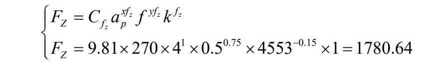
The main cutting force can be calculated by the following [
65]:
The minimum clamping force can be obtained by substituting formulas (2) and (3) into formula (1):
F2 is the clamping force given by a single arm, N;
Fz is the main cutting force, N; μ is the friction coefficient between the clamping claw and the surface of the hub flange;
f2 is the frictional force, N;
d is the distance between the friction point and the center of the inner hole of the hub, mm;
Cfz is the coefficient related to tool material;
ap is the depth of the cut;
f is the feed rate.
The minimum clamping force can be calculated as follows:
K is the safety factor, rough machining takes 2.75, ensuring the clamping force is greater than
Fmin, that is, the clamping can be guaranteed.
3.2. Minimal Quantities Lubricant Device
The “Made in China 2025” proposes promoting the development of manufacturing in the direction of intelligent, green, high-end, and service. Green processing is the international trend, and under the push of this international trend, hub production line from pouring type to MQL type of processing conditions become inevitable. Conventional pouring lubrication uses a large amount of mineral oil cutting fluid, which pollutes the environment and harms workers’ health. Using and disposing of the cutting fluid is expensive.
MQL technology is an important solution to the above technical bottlenecks. MQL is the efficient lubrication of machining processes with a very small amount of lubricant, MQL reduces lubricant usage from 60 L/h of castable to 30–100 mL/h [
63,
64,
65,
66]. In addition, the cutting fluid used for MQL is vegetable-oil-based cutting fluid, and vegetable oil has good degradation ability, which not only reduces waste but also improves the processing effect.
Transforming the MQL device on the production line has become inevitable [
67]. The structure of the MQL system is shown in . The MQL system includes the MQL equipment and oil pumps. Compressed gas through the electromagnetic valve is divided into two ways. One part of the gas reaches the nozzle, and the other part of the gas passes through the pneumatic frequency generator to ensure the minimum quantity pneumatic pump is a small amount of lubricating oil pumped out to the nozzle, and the compressed gas and a small amount of lubricating oil in the nozzle are mixed into a mist and sprayed out at a high speed. The MQL oil pumps are composed of a tank body, a solenoid valve, a hydraulic oil pump-specific motor, a hydraulic oil pump, and a liquid level controller. The hydraulic oil pump is mounted on the tank body. The motor specific for the hydraulic oil pump is mounted on the tank cover and is connected to the hydraulic oil pump. A pipeline of an oil outlet of the hydraulic oil pump is connected to a cross-joint. The pipeline is divided into three paths connected to the solenoid valve and then to the oil cup of the micro lubrication apparatus.
The MQL equipment is mounted on the machine tool to provide MQL conditions for hub processing. The MQL device is used to replace the pouring lubrication device [
68]. According to the spindle speed of machine tool processing, the amount of lubricating oil is adjusted. This approach not only enhances the lubrication effect but also reduces the cost and pollution.
. Minimum quantity lubrication device. 1. Gas filter pressure-regulating valve 2. Electromagnetic valve 3. Oil tank 4. Minimum quantity pneumatic pump 5. Oil–gas mixing plant 6. Pneumatic frequency generator 7. Tank body 8. Solenoid valve 9. Hydraulic oil pump-specific motor 10. Hydraulic oil pump 11. Liquid level controller.
4. Trajectory Planning and Efficiency of Loading and Unloading Robot
The loading and unloading robot is responsible for the material transmission between each processing machine tool, machine tool, and roller table, which has a great effect on the processing efficiency of the production line. The robot is shown in , including the existing mechanical arm and manipulator. The center clamping of the clamping plate is achieved by a cylinder-driven crank–slider mechanism, and the clamping block achieves the flexible clamping of the hub. The manipulator has two positions of grasping wheels. The rotation of the mechanical arm to complete the continuity of loading and unloading saves time and increases the processing efficiency.
. Structure diagram of loading and unloading manipulator. 1. Mechanical arm 2. Wheel hub 3. Connecting rod mechanism 4. Clamping plate 5. Clamping block.
The hub manipulator handling trajectory is complex, so the trajectory of the manipulator must be planned to avoid the collision between the machine tool and the loading and unloading manipulator. Taking the material handling between the first vertical machine tool and the second vertical machine tool as an example, the loading and unloading robot to teach points for 9, a pHome point, a transition point, three obstacle avoidance points, a positioning device grab point, a machine tool grab point, and two machine placement points. Three obstacle avoidance points are completed by the offset instruction, as shown in .
. TCP trajectory planning of robot hand.
Simulation is carried out through Robotstodio, and the loading and unloading robot hand TCP trajectory tracking is shown in . The results show the loading and unloading robot can achieve the desired operating results under preset trajectory conditions, and the robot can replace manual handling to improve the work efficiency. In addition, TCP trajectory tracking can be used to determine whether collisions and interference occur, saving actual debugging time and avoiding accidents. Reasonable adjustment of the robot’s operating speed at each path stage can effectively improve the robot’s loading and unloading efficiency. Software runs, the average time to move the wheel hub between the roller table and each machine tool is 27 s. In the conventional workshop, loading and unloading between hub machine tools is completed manually, with an average of about 33 s.
Loading and unloading efficiency improvement are defined as follows:
. TCP trajectory tracking of robot hand.
5. Conclusions
The production and processing technology of automobile wheel hub were analyzed, and intelligent, sustainable manufacturing production line for automobile wheel hub and processing equipment were designed.
1. The machining of automotive wheel hubs was analyzed based on wheel hub geometric feature and machining requirement. The automotive wheel hubs can be classified as a disc cover type component and the main processing method for automotive wheel hubs was turning.
2. Based on the production and processing technology of automobile wheel hub, the overall design of the hub production line was presented. Each production unit used the feeding device to achieve parallel production. The fixture achieved self-positioning and clamping functions through a linkage mechanism and a crank–slider mechanism, respectively. The MQL system was installed on the machine tool not only to ensure the accuracy and quality of processing but also to reduce the waste of resources. The trajectory planning of the robot with dual clamping stations is performed by RobotStodio.
3. The clamping reliability of fixtures and robot path planning were analyzed. The results showed the machining parameters for machining a wheel hub with a diameter of 580 mm are n = 2500 r/min, ap = 4 mm, fz = 0.5 mm/r, and minimum clamping force of the fixture = 10881.75 N. The average time to move the wheel hub between the roller table and each machine tool is 27 s.
Acknowledgments
This research was financially supported by the following organizations: the Special Fund of Taishan Scholars Project (tsqn202211179), the Youth Talent Promotion Project in Shandong (SDAST2021qt12).
Author Contributions
Conceptualization, M.C. and Y.Z.; Methodology, M.C.; Software, B.L.; Validation, Z.Z. and N.Z.; Investigation, M.C.; Data Curation, Y.Z.; Writing – Original Draft Preparation, M.C. and Y.Z.; Writing – Review & Editing, Y.Z.; Supervision, H.W. and L.W.; Funding Acquisition, Y.Z.
Ethics Statement
Not applicable.
Informed Consent Statement
Not applicable.
Funding
The National High Technology Research and Development Program of China (2020YFB2010500); Major scientific and technological innovation project of Shandong Province (2019JZZY020111).
Declaration of Competing Interest
The authors declare that they have no known competing financial interests or personal relationships that could have appeared to influence the work reported in this paper.
References
1.
Dai XZ, Wang Y, Peng ZP, Cheng HB. Prediction Method of Car Ownership Based on Double Logistic Curve Model. J. Chongqing Jiaotong Univ. Nat. Sci. 2019, 38, 21–26. doi:10.3969/j.issn.1674-0696.2019.11.04.
2.
Baheti U, Guo C, Malkin S. Environmentally conscious cooling and lubrication for grinding. In Proceedings of the International Seminar on Improving Machine Tool Performance, San Sebastian, Spain, July 1998; Volume 2; pp. 643–654.
3.
Klocke F, Eisenblätter G. Dry Cutting.
CIRP Ann. Manuf. Technol. 1997,
46, 519–526.
[Google Scholar]
4.
Jia D, Li C, Zhang Y, Zhang D, Zhang X. Experimental research on the influence of the jet parameters of minimum quantity lubrication on the lubricating property of Ni-based alloy grinding.
Int. J. Adv. Manuf. Technol. 2016,
82, 617–630.
[Google Scholar]
5.
Wang C, Xie Y, Qin Z, Lin HS, Yuan YH, Wang QM. Wear and breakage of TiAlN- and TiSiN-coated carbide tools during high-speed milling of hardened steel.
Wear 2015,
336, 29–42.
[Google Scholar]
6.
Jia D, Li C, Zhang D, Zhang Y, Zhang X. Experimental verification of nanoparticle jet minimum quantity lubrication effectiveness in grinding. J. Nanopart. Res. 2014, 16, 1–15. doi:10.1007/s11051-014-2758-7.
7.
Shi Z, Guo S, Liu H, Li C, Zhang Y, Yang M, et al. Experimental Evaluation of Minimum Quantity Lubrication of Biological Lubricant on Grinding Properties of GH4169 Nickel-base Alloy. Surface Technol. 2021, 50, 71–84. doi:10.16490/j.cnki.issn.1001-3660.2021.12.007.
8.
Zhang YB, Li CH. Grinding mechanism, force prediction model and experimental validation of vegetable oil based nanofluids minimum quantity lubrication.
J. Mech. Eng. 2020,
56, 44.
[Google Scholar]
9.
Jia DZ, Li CH, Zhang YB, Yang M, Cao HJ, Liu B, et al. Grinding Performance and Surface Morphology Evaluation of Titanium Alloy Using Electric Traction Bio Micro Lubricant.
J. Mech. Eng. 2022,
58, 198–211.
[Google Scholar]
10.
Li B, Li C, Zhang Y, Wang Y, Yang M, Jia D, et al. Effect of the physical properties of different vegetable oil-based nanofluids on MQLC grinding temperature of Ni-based alloy.
Int. J. Adv. Manuf. Technol. 2017,
89, 3459–3474.
[Google Scholar]
11.
Li B, Li C, Zhang Y, Wang Y, Jia D, Yang M. Grinding temperature and energy ratio coefficient in MQL grinding of high-temperature nickel-base alloy by using different vegetable oils as base oil.
Chin. J. Aeronaut. 2016,
29, 1084–1095.
[Google Scholar]
12.
Yokokawa K, Yokokawa M. Meet ISO14000 environmental protection - do not use cutting oil cold air grinding (4) the first cold air the grinding process.
Mach. Tools 1999,
43, 121–125.
[Google Scholar]
13.
Anqi AE, Li C, Dhahad HA, Sharma K, Attia EA, Abdelrahman A, et al. Effect of combined air cooling and nano enhanced phase change materials on thermal management of lithium-ion batteries.
J. Energy Storage 2022,
52, 104906.
[Google Scholar]
14.
Liu J, Han R, Zhang L, Guo H. Study on lubricating characteristic and tool wear with water vapor as coolant and lubricant in green cutting.
Wear 2007,
262, 442–452.
[Google Scholar]
15.
Cui X, Li C, Zhang Y, Ding W, An Q, Liu B, et al. A comparative assessment of force, temperature and wheel wear in sustainable grinding aerospace alloy using bio-lubricant.
Front. Mech. Eng. 2022,
18, 3.
[Google Scholar]
16.
Cui X, Li C, Zhang Y, Said Z, Debnath S, Sharma S, et al. Grindability of titanium alloy using cryogenic nanolubricant minimum quantity lubrication.
J. Manuf. Processes 2022,
80, 273–286.
[Google Scholar]
17.
Wang X, Li C, Zhang Y, Ali HM, Sharma S, Li R, et al. Tribology of enhanced turning using biolubricants: A comparative assessment.
Tribol. Int. 2022,
174, 107766.
[Google Scholar]
18.
Kaynak Y, Karaca HE, Noebe RD, Jawahir IS. Tool-wear analysis in cryogenic machining of NiTi, shape memory alloys: A comparison of tool-wear performance with dry and MQL machining.
Wear 2013,
306, 51–63.
[Google Scholar]
19.
Zhang X, Li C, Zhang Y, Wang Y, Li B, Yang M, et al. Lubricating property of MQL grinding of Al
2O
3/SiC mixed nanofluid with different particle sizes and microtopography analysis by cross-correlation.
Precis. Eng. 2017,
47, 532–545.
[Google Scholar]
20.
Debnath S, Reddy MM, Yi QS. Environmental friendly cutting fluids and cooling techniques in machining: a review.
J. Clean. Prod. 2014,
83, 33–47.
[Google Scholar]
21.
Li H, Zhang Y, Li C, Zhou Z, Nie X, Chen Y, et al. Cutting fluid corrosion inhibitors from inorganic to organic: Progress and applications.
Korean J. Chem. Eng. 2022,
39, 1107–1134.
[Google Scholar]
22.
Li HG, Zhang YB, Li CH, Zhou Z, Nie X, Chen Y, et al. Extreme pressure and antiwear additives for lubricant: academic insights and perspectives.
Int. J. Adv. Manuf. Technol. 2022,
120, 1–27.
[Google Scholar]
23.
Yang Y, Gong Y, Li C, Wen X, Sun J. Mechanical performance of 316L stainless steel by hybrid directed energy deposition and thermal milling process.
J. Mater. Process. Technol. 2021,
291, 117023.
[Google Scholar]
24.
Hong SY, Zhao Z. Thermal aspects, material considerations and cooling strategies in cryogenic machining.
Clean Prod. Processes 1999,
1, 107–116.
[Google Scholar]
25.
Wang XM, Zhang JC, Wang XP, Zhang YB, Liu B, Luo L, et al. Effect of nanoparticale volume on grinding peformance of titanium alloy in cryogenic air minimum quantity lubrication.
Diam. Abras. Eng. 2020,
40, 23–29.
[Google Scholar]
26.
Wang X, Li C, Zhang Y, Ding W, Yang M, Gao T, et al. Vegetable Oil-based Nanofluid Minimum Quantity Lubrication Turning: Academic Review and Perspectives.
J. Manuf. Processes 2020,
59, 76–97.
[Google Scholar]
27.
Gao T, Zhang Y, Li C, Wang Y, Chen Y, An Q, et al. Fiber-reinforced composites in milling and grinding: machining bottlenecks and advanced strategies.
Front. Mech. Eng. 2022,
17, 24.
[Google Scholar]
28.
Sadeghi MH, Haddad MJ, Tawakoli T, Emami M. Minimal quantity lubrication-MQL in grinding of Ti–6Al–4V titanium alloy.
Int. J. Adv. Manuf. Technol. 2009,
44, 487–500.
[Google Scholar]
29.
Yin Q, Li C, Zhang Y, Yang M, Jia D, Hou Y, et al. Spectral analysis and power spectral density evaluation in Al2O3 nanofluid minimum quantity lubrication milling of 45 steel.
Int. J. Adv. Manuf. Technol. 2018,
97, 129–145.
[Google Scholar]
30.
Zhang Y, Li C, Yang M, Jia D, Wang Y, Li B, et al. Experimental evaluation of cooling performance by friction coefficient and specific friction energy in nanofluid minimum quantity lubrication grinding with different types of vegetable oil.
J. Clean. Prod. 2016,
139, 685–705.
[Google Scholar]
31.
Tawakoli T, Hadad MJ, Sadeghi MH, Daneshi A, Stöckert S, Rasifard A. An experimental investigation of the effects of workpiece and grinding parameters on minimum quantity lubrication-MQL grinding.
Int. J. Mach. Tools Manuf. 2009,
49, 924–932.
[Google Scholar]
32.
Duan ZJ, Li CH, Zhang YB, Dong L, Bai XF, Yang M, et al. Milling surface roughness for 7050 aluminum alloy cavity influenced by nozzle position of nanofluid minimum quantity lubrication.
Chin. J. Aeronaut. 2021,
34, 33–53.
[Google Scholar]
33.
Duan ZJ, Li CH, Zhang YB, Yang M, Gao T, Liu X, et al. Mechanical behavior and Semiempirical force model of aerospace aluminum alloy milling using nano biological lubricant.
Front. Mech. Eng. 2022,
18, 4.
[Google Scholar]
34.
Lee PH, Nam TS, Li C, Lee SW. Environmentally-Friendly Nano-fluid Minimum Quantity Lubrication (MQL) Meso-scale Grinding Process Using Nano-diamond Particles. In Proceedings of the 2010 International Conference on Manufacturing Automation, Hong Kong, China, 13–15 December 2010.
35.
Yang M, Li C, Said Z, Zhang Y, Li R, Debnath S, et al. Semiempirical heat flux model of hard-brittle bone material in ductile microgrinding.
J. Manuf. Processes 2021,
71, 501–514.
[Google Scholar]
36.
Jia DZ, Zhang N Q, Liu B, Zhou Z, Wang X, Zhang Y, et al. Particle size distribution characteristics of electrostatic minimum quantity lubrication and grinding surface quality evaluation. Diam. Abras. Eng. 2021, 41, 89–95. doi:10.13394/j.cnki.jgszz.2021.3.0013.
37.
Wu X, Li C, Zhou Z, Nie X, Chen Y, Zhang Y, et al. Circulating purification of cutting fluid: an overview.
Int. J. Adv. Manuf. Technol. 2021,
117, 2565–2600.
[Google Scholar]
38.
Liu M Z, Li CH, Cao HJ, Zhang S, Chen Y, Liu B, et al. Research Progress and Application of Cryogenic Minimum Quantity Lubrication Machining Technology.
China Mech. Eng. 2022,
33, 529–550.
[Google Scholar]
39.
Liu MZ, Li CH, Zhang YB, An Q, Yang M, Gao T, et al. Cryogenic minimum quantity lubrication machining: From mechanism to application.
Front. Mech. Eng. 2021,
16, 649–697.
[Google Scholar]
40.
Zhang YB, Li CH, Jia DZ, Li BK, Wang YG, Yang M, et al. Experimental Evaluation of the Workpiece Surface Quality of MoS
2/CNT Nanofluid for Minimal Quantity Lubrication in Grinding.
J. Mech. Eng. 2018,
54, 161–170.
[Google Scholar]
41.
Xu WH, Li CH, Zhang YB, Ali HM, Sharma S, Li R, et al. Electrostatic atomization minimum quantity lubrication machining: from mechanism to application.
Int. J. Extrem. Manuf. 2022,
4, 042003.
[Google Scholar]
42.
Sharma P, Said Z, Kumar A, Nizetic S, Pandey A, Hoang AT, et al. Recent advances in machine learning research for nanofluid-based heat transfer in renewable energy system.
Energy Fuels 2022,
36, 6626–6658.
[Google Scholar]
43.
Yang M, Li CH, Zhang YB, Jia DZ, Zhang XP, Li RZ. A New Model for Predicting Neurosurgery Skull Bone Grinding Temperature Field.
J. Mech. Eng. 2018,
54, 215–222.
[Google Scholar]
44.
Yang M, Li CH, Zhang YB, Wang YG, Li BK, Li RZ. Theoretical Analysis and Experimental Research on Temperature Field of Microscale Bone Grinding under Nanoparticle Jet Mist Cooling.
J. Mech. Eng. 2018,
54, 194–203.
[Google Scholar]
45.
Yang M, Li CH, Zhang YB, Wang YG, Li BK, Jia DZ, et al. Research on microscale skull grinding temperature field under different cooling conditions.
Appl. Therm. Eng. 2017,
126, 525–537.
[Google Scholar]
46.
Wang XM, Zhang J C, Wang XP, Zhang YB, Luo L, Zhao W, et al. Temperature Field Model and Verification of Titanium Alloy Grinding under Different Cooling Conditions.
China Mech. Eng. 2021,
32, 572–578.
[Google Scholar]
47.
Wang XM, Li CH, Zhang YB, Chen Y, Cao HJ, Liu B, et al. Experimental Evaluation of Wear Mechanism and Grinding Performance of SG Wheel in Machining Nickel-based Alloy GH4169. Surface Technol. 2022, 51, 114. doi:10.16490/j.cnki.issn.1001-3660.2022.09.001.
48.
He F, Zhuang LZ, He GY, Li HX, Yi GY. A356 Aluminum Alloy for Automobile Wheel Hubs-Research Progress and Influence of Alloying Elements on Its Microstructure and Properties.
Foundry 2021,
70, 431–437.
[Google Scholar]
49.
Shi ZL. An Analysis on the Perspective of China’s Automobile’s Hubcap Industry. Econ. Survey 2004, 03, 61–64. doi:10.15931/j.cnki.1006-1096.2004.03.019.
50.
Niu T, Sun JJ, Zhang YY. Technical Analysis of Automatic Production Line for Flexible Machining of Automobile Wheel Hubs. Mach. Build. Automat. 2017, 46, 216–218. doi.10.19344/j.cnki.issn1671-5276.2017.06.060.
51.
Xu SQ, Zhang YB, Zhou ZM, Liu B, Li CH. Design of automated and cleaner production line for wheel hub in automobile manufacturing. Manuf. Technol. Mach. Tool 2022, 04, 32–37. doi:10.19287/j.mtmt.1005-2402.2022.04.004.
52.
Zheng W, Sun JJ, Niu T, Ma CB, Yu QP, Zhang YY. Design and Analysis of A Kind of Automobile Hub Flexible Machining Fixture. Mach. Des. Res. 2019, 35, 132–136. doi:10.13952/j.cnki.jofmdr.2019.0160.
53.
Zheng W, Sun JJ, Ma CB, Yu QP, Niu T, Ma LB. Analysis on the positioning error of the automotive wheel hub’s flexible machining fixture. J. Mach. Des. 2021, 38, 46–52. doi.10.13841/j.cnki.jxsj.2021.03.007.
54.
Hou YT, Li LC, Gu JN, Mao WY. Vehicle Hub Type Recognition Based on SURF Features. Mach. Des. Manuf. 2021, 08, 5–7. doi:10.19356/j.cnki.1001-3997.2021.08.002.
55.
Zhao HW, Zhao YC, Qi XY, Li F. Research on Surface Defect Inspection Algorithms of Automobile Hub Based on Deep Learning. Modul. Mach. Tool Automat. Manuf. Tech. 2019, 11, 112–115. doi:10.13462/j.cnki.mmtamt.2019.11.028.
56.
Zhu CP, Yang YB. Online Detection Algorithm of Automobile Wheel Surface Defects Based on Improved Faster-RCNN Model. Surface Technol. 2020, 49, 359–365. doi:10.16490/j.cnki.issn.1001-3660.2020.06.044.
57.
Liang YF, Zhu ZK. The design and study of the overall architecture of the intelligent manufacturing system for the automobile hub production line. Ind. Instrum. Automat. 2018, 04, 61–64. doi:10.3969/j.issn.1000-0682.2018.04.015.
58.
Yin CT. Auto wheel manufacturing system design based on the CPS. Manuf. Technol. Mach. Tool 2017, 10, 142–146. doi:10.19287/j.cnki.1005-2402.2017.10.033.
59.
Shi L. Design and analysis of flexible Machining fixture for automobile wheel hub under cutting Force. Internal Combust. Engine Parts 2020, 15, 75–76. doi.10.19475/j.cnki.issn1674-957x.2020.15.029.
60.
Liu DW, Liu HJ, Zhou ZM, Chen Y, Liu B, Zhang NQ, et al. Design and Analysis of Flexible Fixture for Aluminum Alloy Hub.
Tool Eng. 2022,
56, 75–82.
[Google Scholar]
61.
Das S. Design and Weight Optimization of Aluminium Alloy Wheel.
Int. J. Sci. Res. Publ. 2014,
4, 1–12.
[Google Scholar]
62.
Mao JH, Zhang YX, Jiang LW, Qu P. Analysis on microstructure and properties of A356 cast aluminum alloy wheel hub.
China Metall. 2021,
31, 66–71.
[Google Scholar]
63.
Wang ML, Zuo JM, Zhu H, Hu YY. Modeling and dynamic simulation of high speed cutting temperature field based on 3-D finite element analysis. Modern Manuf. Eng. 2010, 02, 80–84. doi.10.16731/j.cnki.1671-3133.2010.02.003.
64.
Davim JP, Sreejith PS, Gomes R, Peixoto C. Experimental studies on drilling of aluminium (AA1050) under dry, minimum quantity of lubricant, and flood-lubricated conditions.
Proc. Inst. Mech. Eng. Part B J. Eng. Manuf. 2006,
220, 1605–1611.
[Google Scholar]
65.
Tang L, Zhang Y, Li C, Zhou Z, Nie X, Chen Y, et al. Biological stability of water-based cutting fluids: progress and application. Chin. J. Mech. Eng. 2022, 35, 1–24. doi:10.1186/s10033-021-00667-z.
66.
Zhang Z, Sui M, Li C, Zhou Z, Liu B, Chen Y, et al. Residual stress of MoS2 nano-lubricant grinding cemented carbide. Int. J. Adv. Manuf. Technol. 2021. doi:10.1007/s00170-022-08660-z.
67.
Zhang J, Li C, Zhang Y, Yang M, Jia D, Liu G, et al. Experimental assessment of an environmentally friendly grinding process using nanofluid minimum quantity lubrication with cryogenic air.
J. Clean. Prod. 2018,
193, 236–248.
[Google Scholar]
68.
Bai X, Li C, Dong L, Yin Q. Experimental evaluation of the lubrication performances of different nanofluids for minimum quantity lubrication (MQL) in milling Ti-6Al-4V.
Int. J. Adv. Manuf. Technol. 2019,
101, 2621–2632.
[Google Scholar]