
Binder Jetting 3D Printing Utilizing Waste Algae Powder: A Feasibility Study

Author Information
Other Information
1
Department of Industrial & Systems Engineering, Texas A&M University, College Station, TX 77843, USA
2
National Renewable Energy Laboratory, Golden, CO 80401, USA
*
Authors to whom correspondence should be addressed.
Received: 20 August 2024 Accepted: 12 October 2024 Published: 15 October 2024

© 2024 The authors. This is an open access article under the Creative Commons Attribution 4.0 International License (https://creativecommons.org/licenses/by/4.0/).
Intell. Sustain. Manuf.
2024,
1(2), 10016;
DOI: 10.70322/ism.2024.10016
ABSTRACT:
This
paper reports, for the first time in the literature, a preliminary study to investigate
the feasibility of utilizing waste algae powder (byproducts of biofuel
manufacturing from algae) in binder jetting 3D printing to produce
environmentally friendly products. In this study, the algae powder’s morphology
and particle size distribution were characterized using scanning electron
microscopy and particle size analyzer, respectively, and the flowability was
assessed through apparent density and repose angle. The algae powder
successfully printed the cylindrical, cubic, and gyroid parts on a binder
jetting 3D printer. Results show that it is feasible to print parts with binder
jetting 3D printing utilizing waste algae powder. The use of waste algae powder
in additive manufacturing offers a novel approach to upcycling waste algae
powder into valuable products for various applications such as packaging and
construction.
Keywords:
Additive manufacturing; Binder jetting 3D printing; Gyroid sample; Sustainability; Waste algae powder

1. Introduction
Global warming presents critical environmental, economic, and social challenges. The Intergovernmental Panel on Climate Change reports that human activities have increased greenhouse gas emissions, significantly increasing global surface temperature [1]. Since 1980, climatological events involving extreme temperatures, droughts, and forest fires have increased fourfold, while meteorological events such as extreme storms have doubled [2]. These climatic changes are also destabilizing ecosystems. For instance, the unprecedented early flowering of cherry blossoms in Japan along with the altered migration patterns of birds across Europe, are clear indicators of these environmental disruptions [3,4]. Such changes threaten biodiversity and the survival of numerous species. Furthermore, climate change significantly impacts human livelihoods and health by exacerbating food and water insecurity, increasing the prevalence of climate-related diseases, and contributing to economic instability.
Fossil fuels (coal, oil, and gas), consumed to meet 80% of global energy needs, are a major source of greenhouse gases (GHGs), including CO2, the primary driver of climate change [5]. In addition, fossil fuels are projected to be critically depleted in the next 50 years [6]. Given the finite nature of fossil fuels and their extensive environmental impacts, there is an urgent need to transition to renewable energy sources such as biofuels that emit little to no GHGs [7,8]. During their growth phase, the plants used for biofuel production absorb CO2 from the atmosphere, which can offset the GHG emissions during their combustion [9]. This creates a more balanced carbon cycle compared to fossil fuels [10]. Furthermore, biofuels can enhance energy security by diversifying energy sources and reducing reliance on imported oil. They can also contribute to economic stability and job creation, particularly in rural areas.
First-generation biofuels, such as ethanol from corn and biodiesel from soybean oil, compete with food production and have sustainability issues [11,12]. Second and third-generation biofuels offer a more favorable carbon balance and lower environmental impact. Second-generation biofuels are produced from non-food waste, such as agricultural residues [13,14,15,16,17], while third-generation biofuels are derived from algae [18,19,20], which does not compete with food crops for arable land. Algae can yield higher amounts of lipids for producing biofuels per unit area of growing space compared to terrestrial crops [21]. Despite the promising potential of algae as a biofuels source, the economic viability of large-scale production remains a significant challenge. The process of cultivating, harvesting, and converting algae into biofuels is resource-intensive and costly [22]. Current estimates suggest that the cost of producing algae-based biofuels is significantly higher than that of fossil fuels [23], making algae biofuels less competitive.
One approach to increase the competitiveness of algae biofuels is to convert waste algae (from the production of algae biofuels) into valuable products. The large-scale production of biofuels from algae leads to the accumulation of substantial waste algae, which has historically been overlooked in terms of potential secondary uses [9]. Additive manufacturing, or 3D printing, is a process that creates objects by adding material layer by layer from a digital model [24]. It can be used to turn waste algae powder, a byproduct of biofuel production, into valuable products to be used in packaging and construction or as consumer goods. Binder jetting 3D printing has the ability to produce complex geometries, is more suitable for large-scale production [25], allows for a wide range of materials (including metal, ceramic, and composite materials), and does not require support structures [26,27,28]. Additionally, binder jetting 3D printing offers a good surface finish. The valorization of waste algae powder as a material for binder jetting 3D printing presents an opportunity to increase the economic sustainability of algae biofuels.
Algae powder has been utilized as filler materials in filaments for filament-based 3D printing, such as Fused Deposition Modeling (FDM), aka Fused Filament Fabrication (FFF) [29,30], and as additives in mixtures for extrusion-based 3D printing [31,32]. However, there are no reported studies on using algae powder in binder jetting 3D printing. The objective of this study is to demonstrate the feasibility of binder jetting 3D printing with waste algae powder. In this study, parts of varying geometric complexity were printed using binder jetting 3D printing. The paper focuses on characterizing the flowability of the algae powder, analyzing its particle morphology and size distribution, and assessing the printed parts properties (density and compressive strength).
The paper is structured as follows. Section 2 details the experimental procedures for the characterization of algae powder, measurement of compatibility between algae powder and binder, binder jetting 3D printing, and measurements of properties of printed parts. Section 3 presents the results. Finally, Section 4 discusses conclusions and future research directions.
2. Experimental Procedure
2.1. Characterization of Algae Powder
The algae powder (Spirulina blue-green algae) in this study was purchased from Carlyle Nutritionals (New York, NY, USA). The received algae powder was sieved using a 250 µm sieve (ASTM No. 60). Then the sieved algae powder was used directly in binder jetting 3D printing. No additives were added to the powder, and the powder did not go through additional steps (such as mixing). A field emission scanning electron microscopy (FE-SEM: JSM7500, RRID: SCR_022202, JEOL, Tokyo, Japan) was used to reveal the algae powder particles’ shape, size, and surface morphology. The algae powder used for FE-SEM imaging underwent a surface treatment involving a 5-nm platinum (Pt) coating. Images were taken at magnifications of 100× and 2500×.
Several techniques exist for measuring powder flowability, including shear cell testing [33], flow rate through an orifice [34], dynamic flow testing [33,35], and measuring the apparent density and repose angle of the powder [36,37]. In this study, apparent density and repose angle were measured to evaluate powder flowability because the authors had access to needed facilities and had conducted many studies [38,39,40] in the past using this technique. A higher apparent density and a lower repose angle usually signify better flowability [41]. The apparent density of the powder was determined using a Hall flowmeter (DF-1-02, HongTuo, Dongguan, China), as depicted in Figure 1a [42]. The Carney funnel was utilized to measure powder’s apparent density [39]. The apparent density of the algae powder was measured three times. The mean of apparent density values from these three measurements are presented in Section 3.1. For each apparent density measurement, the mass of the empty density cup was initially recorded. The funnel was then filled with algae powder., As seen in Figure 1a, the funnel opening is narrower than the funnel. Due to gravity, the powder was allowed to fall, filling the cup beneath the funnel, forming a cone, and eventually overflowing as shown in Figure 1b. The cone was gently removed with a spatula, followed by weighing the cup with the powder inside. The net powder mass within the cup was divided by the cup volume (25 cm3, as predefined in the standard [39]) to calculate the apparent density for each measurement.
The Hall flowmeter was also used to measure the repose angle of the algae powder [43]. The repose angle of the algae powder was measured three times. The mean of repose angle values calculated from these three measurements are presented in Section 3.1. For each measurement, the funnel was filled with algae powder. As seen in Figure 1a, the funnel opening is narrower than the funnel. Due to gravity, powder was allowed to fall, filling the cup beneath the funnel and forming a cone, as shown in Figure 1b. To quantify the diameter of the cone base (d) and the height of the cone (h), the side-view images of the come were taken by iPhone. The images were processed using IMAGEJ software. The repose angle was then calculated using the following Equation (1):
2.2. Measurement of Compatibility between Algae Powder and Binder
In binder jetting 3D printing, the binder and powder should be compatible with print parts with sufficient strength [44]. Powder-binder compatibility experiments were conducted on algae powder with an aqueous binder (AquaFuse™, BA005, ExOne Company, North Huntington, PA, USA), which is commonly used for the ExOne Innovent+ binder jetting 3D printer. More details about powder-binder compatibility experiments can be found in the literature [45,46]. Four selected steps in the procedure are shown in Figure 2 and described below. Step 1: The powder was sieved using a screen with an opening size of 250 µm (ASTM No. 60) and dispensed on a flat pan. Step 2: A roller was used to roll the powder into a uniform layer. Step 3: Three drops of aqueous binder were dropped on one selected area of the powder layer to form one of the four binder-powder samples. Afterward, the flat pan containing the binder-powder samples was placed in an oven at 100 °C for 5 h for curing. After curing, the loose powder surrounding the samples was removed using a brush. Step 4: The powder-binder samples were visually evaluated.
2.3. Binder Jetting 3D Printing
A binder jetting 3D printer (Innovent+, ExOne Company, North Huntington, PA, USA) and an aqueous binder (BA005, ExOne Company, North Huntington, PA, USA) were used for printing parts. Binder jetting 3D printing is illustrated in Figure 3. It begins with lowering the build platform by the distance of the layer thickness (LT). Subsequently, a heat lamp passes over the built platform to dry the powder bed (Figure 3a). Next, the hopper containing the feedstock powder moves horizontally with the counter-rotating roller (from right to left) across the build platform, depositing the powder on the powder bed (Figure 3b). A forward-rotating roller then spreads the powder from left to right (Figure 3c). Finally, the print head moves over the powder bed, jetting the binder onto specific areas as per the 3D model of the part being printed (Figure 3d). The process is repeated layer by layer until the entire part is fully printed.
The values of printing parameters are listed in Table 1. Descriptions of the parameters can be found in the literature [47]. These values were chosen based on preliminary trials during which the qualities of dispensing, spreading, and printing were evaluated to ensure they were acceptable. Based on the particle size distribution analysis, the mean particle size of the algae powder was 100 μm. In binder jetting 3D printing, layer thickness should be approximately twice the mean particle size [48,49]. As a result, layer thickness in the binder jetting experiments was selected as 200 μm. A binder saturation of 50% and a powder packing rate of 10% were chosen to strike a balance between adhesion and material efficiency. A roller traverse speed of 10 mm/sec, a roller rotation speed of 300 rpm, roughening roller rotation speed of 50 rpm, and recoat speed of 40 mm/s was selected. After printing, green parts were placed in an oven (DX402C, Yamato Scientific, Tokyo, Japan) at 125 °C for 5 h to cure the binder in the printed parts. This curing process was essential to provide the green parts with sufficient mechanical strength [40,50].
In a single batch of printing, three cubic parts (10 mm × 10 mm × 10 mm), three cylindrical parts (6.35 mm in diameter and 12.7 mm in height), and three cubic gyroid parts (10 mm × 10 mm × 10 mm), as shown in Figure 4, were fabricated. The designs of these parts were created using SolidWorks 2019, a CAD software.
2.4. Measurements of Properties of Printed Parts
Green density and relative density of the three cubic parts were measured, while the theoretical density of algae was obtained from the literature [51]. Green density refers to the density of a printed part (after curing). Relative density was the ratio of measured green density to theoretical density expressed as a percentage. Theoretical density, based on the material’s crystal structure and atomic weights, represents the maximum possible density of the material. Three printed cubic parts were used for green density measurement. The dimensions (length, width, and height) of the parts were measured using a slide caliper (500-196-30 Digimatic 0-6″/150MM Stainless Steel Digital Caliper, Mitutoyo, Japan) and their masses were determined using a weight scale. The green density of the cubic parts was calculated by dividing their mass by volume.
Three printed cylindrical parts were used for compressive strength measurement. Compressive strength was measured using a Universal Testing Machine equipped with a 2.5 kN load cell, operating at a strain rate of 1 mm/s [52]. Upon fracture of the sample, the load was released.
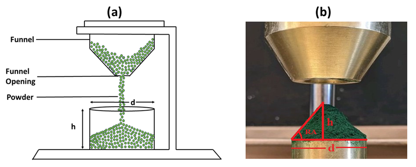
Figure 1. Illustration of Hall flowmeter for (<b>a</b>) measurement of apparent density, (<b>b</b>) measurement of repose angle.
```latexRA=\tan^{-1}\frac{2h}d```
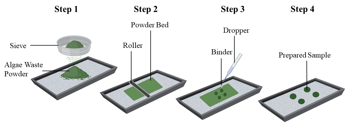
Figure 2. Selected steps in compatibility experiments.
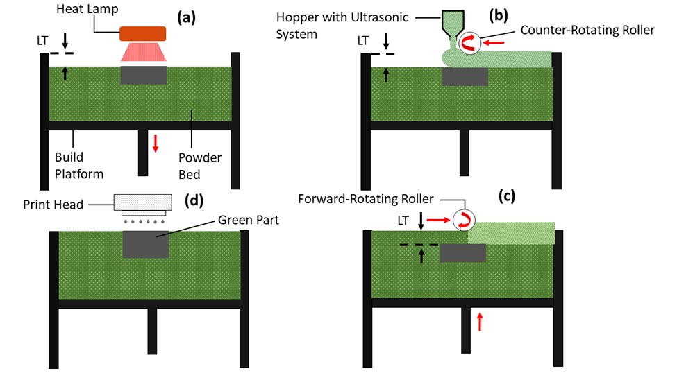
Figure 3. Binder jetting 3D printing (<b>a</b>) a heat lamp passes over the built platform to dry the powder bed, (<b>b</b>) the hopper containing the feedstock powder moves horizontally (from right to left) across the build platform, (<b>c</b>) a roller spreads the powder in a forward-rotating motion from left to right, and (<b>d</b>) the print head moves over the powder bed jetting the binder onto specific areas.
Table 1. Printing parameters and their values used in binder jetting 3D printing of algae powder.

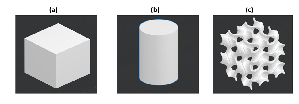
Figure 4. CAD designs of printed parts by SolidWorks (<b>a</b>) cubic; (<b>b</b>) cylindrical, and (<b>c</b>) gyroid.
3. Results and Discussion
3.1. Particle Size Distribution and Flowability of As-Received Algae Powder
Figure 5 shows some FE-SEM images of algae powder. It can be seen that the shape of the as-received algae powder particles was approximately round (more like a potato-shape). The size of these particles was relatively uniform. These round-shaped powder particles were suitable for powder dispensing and powder spreading in binder jetting [53]. Figure 6 shows the particle size distribution of algae powder. The size distribution approximately followed a Gaussian distribution with an average diameter of 100 μm and a standard deviation of 30 μm.
Two flowability metrics (apparent density and repose angle) were measured for the algae powder. Their values are shown in Table 2. As comparisons, the flowability metrics values of other powders are also included in Table 2.
According to Carr’s classification of flowability, the algae powder used in this study was “very cohesive” [54,55]. The algae powder apparent density and repose angle were similar to those of alumina nanopowder and fine silica-based ceramic powder used in binder jetting 3D printing in previous studies [39,40]. For the alumina nanopowder, the apparent density was 0.46 g/cm3, and the repose angle was 67.80° [39]. For the fine silica-based ceramic powder, the apparent density was 0.41 g/cm3, and the repose angle was 52.1° [40]. It was observed that the algae powder flew from the hopper of the binder jetting 3D printer quite consistently, and a smooth powder bed was formed (as shown in Figure 7).
3.2. Results of Compatibility between Binder and Algae Powder
Figure 8 shows the images of the binder-powder samples obtained in the compatibility experiment. These samples did not exhibit visible defects, such as cracks, delamination, or unbound powder. This indicates that the algae powder was adequately bonded by the aqueous binder (AquaFuse™), confirming that the algae powder was compatible with the aqueous binder and suitable for the ExOne Innovent+ binder jetting printer. The compatibility test was visual and qualitative. It was a simple preliminary test intended to make sure that the algae powder could stick together by the aqueous binder before moving forward with binder jetting printing. This could usually be ensured if there were no visible defects like delamination or porosity.
3.3. Images of Printed Parts
Figure 9 shows printed parts using binder jetting 3D printing from algae powder. The surfaces of these printed parts look smooth and do not exhibit visible defects. The printed gyroid parts demonstrate the feasibility of printing complex structures using binder jetting 3D printing from algae powder. The mean and standard deviation of green density were 0.70 g/cm3 and ±0.013, respectively. From the literature, the theoretical density of the algae powder (spirulina) is 1.18 g/cm3 [56]. Thus, the relative green density was calculated at 59.3%. It has been reported that parts printed by binder jetting 3D printing had a relative density of 45% for alumina powder [57] and from 44.5% to 58.8% for stainless steel 316 L [58,59,60,61,62].
3.4. Properties (Density and Compressive Strength) of Printed Parts
Figure 10 shows the engineering stress-strain behavior (under compression) of the printed cylindrical parts (after being cured at 125 °C for 5 h). The x-axis is engineering strain, the ratio of the change in length (deformation) to the original length. The y-axis is engineering stress (N/mm2), the test sample’s load per unit (original) area. The peak stress (at a strain of approximately 0.07) was 1.3 N/mm2, indicating the compressive strength of the printed part. As a comparison, binder jetting 3D printed parts from silica-based ceramic powder, after curing, had a compressive strength of 0.4 N/mm2 [40]. The silica-based ceramic powder particle sizes were comparable to those of the algae powder in this study. Besides biomaterials such as biphasic calcium phosphate, the compressive strength following binder jetting 3D printing was 0.45 MPa [63], while hydroxyapatite powder exhibited a compressive strength of 5.63 MPa [64].
Figure 11 shows a fractured cylindrical part after the compressive testing. As shown in Figure 10, the stress-strain curve dropped sharply after the stress exceeded the compressive strength, indicating that the fracture was brittle in nature.
Table 3 presents the measured properties of the 3D printed parts. The compressive strength of the printed parts is suitable for various applications, including packaging materials that provide cushioning for fragile items, horticultural aids such as decomposable plant pots and seed trays, disposable culinary items like utensils and plates, lightweight decorative elements, and educational models or toys.
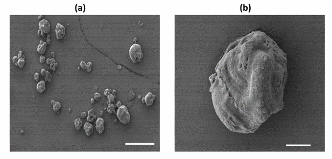
Figure 5. FE-SEM images of algae powder with the scale bar being 200 µm for (<b>a</b>) and 20 µm for (<b>b</b>).
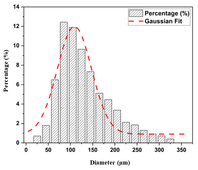
Figure 6. Particle size distribution of algae powder.
Table 2. Flowability (apparent density and repose angle) of algae powder with comparison with powder.
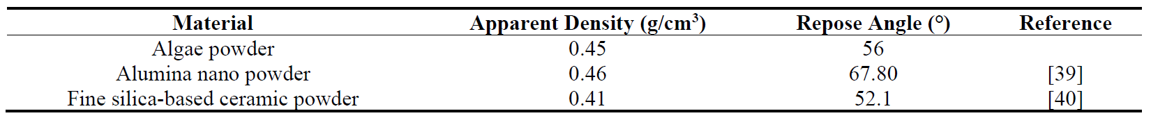
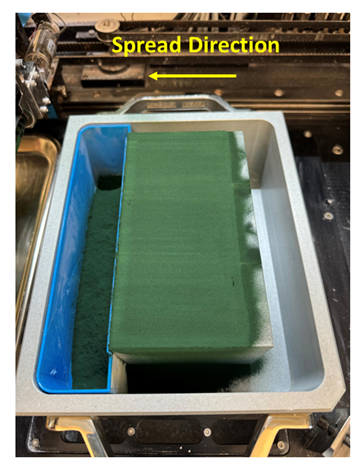
Figure 7. A smooth algae powder bed.
Figure 8. Compatibility experiment samples of algae powder with aqueous binder.
Figure 9. Printed parts using binder jetting 3D printing from algae powder (<b>a</b>) cubic, (<b>b</b>) cylindrical, and (<b>c</b>) gyroid. (Scale bar: 5 mm).
Figure 10. Engineering stress-strain behavior of printed part from algae powder.
Figure 11. Fractured cylindrical part after compressive test (scale bar: 5 mm).
Table 3. Properties of 3D printed parts.

4. Conclusions and Future Research Directions
This preliminary investigation demonstrates the potential of waste algae powder (a byproduct of biofuel manufacturing) as feedstock powder for binder jetting 3D printing. The findings indicate that the particle shape, size distribution, and flowability of the algae powder are well-suited for binder jetting 3D printing. Specifically, the apparent density and repose angle of the algae powder shows that the algae powder has adequate flowability for consistent powder spreading. Apparent density and repose angle were used in this study for a preliminary evaluation of powder flowability, as they are simple and relevant to powder dispensing and spreading. However, advanced methods like shear cell testing [33] and dynamic flow testing [33,35] should provide more detailed insights into how the powder behaves under stress and during movement. The authors plan to use these advanced methods in their future research to further study the algae powder for binder jetting 3D printing.
Moreover, the algae powder exhibits good compatibility with the aqueous binder used in the ExOne Innovent+ binder jetting 3D printer. Printed parts had a sufficient mechanical strength for some applications in packaging and construction or as consumer goods. The successful fabrication of intricate gyroid structures underscores the capability to produce parts with complex geometries.
In their future studies, the authors will study other mechanical properties (such as tensile strength and impact resistance) of printed parts and characterize their dimensional accuracy, structural integrity, and porosity of printed parts. The authors will also systematically study the effects of printing parameters (such as layer thickness, compaction thickness, and binder saturation) on the achievable geometries. Future research will also include the degradability of algae-based parts, life cycle analysis, and the long-term performance of printed parts under various environmental conditions.
Acknowledgments
The authors would like to acknowledge that the characterization part of this work was performed at the Texas A&M University Materials Characterization Core Facility (RRID:SCR_022202). The authors extend their special thanks to Yordanos Bisrat for assistance with scanning electron microscopy (SEM) and to Wilson Serem for conducting particle size distribution (PSD) analysis.
Author Contributions
Ethics Statement
Not applicable.
Informed Consent Statement
Funding
This research received no external funding.
Declaration of Competing Interest
The authors declare that they have no known competing financial interests or personal relationships that could have appeared to influence the work reported in this paper.
References
1.
WMO Warning: 1.5 Degree C Warming Breach Very Soon & with Increasing Frequency. Act Now! 2023. Available online: https://wmo.int/news/media-centre/global-temperature-likely-exceed-15degc-above-pre-industrial-level-temporarily-next-5-years (accessed on 30 May 2024).
2.
Bolan S, Padhye L, Jasemizad T, Govarthanan M, Karmegam N, Wijesekara H, et al. Impacts of climate change on the fate of contaminants through extreme weather events. Sci. Total Environ. 2023, 909, 168388. [Google Scholar]
3.
Mikami T. The Climate of Japan: Present and Past; Springer Nature: Singapore, 2023; Volume 77.
4.
Ranjith M, Chellappan M, Chaudhary V, Sreejeshnath K. Bird pests: Damage and ecofriendly management: Management of depredatory birds. Ann. Arid Zone 2023, 62, 361–372. [Google Scholar]
5.
Siddik M, Islam M, Zaman A, Hasan M. Current status and correlation of fossil fuels consumption and greenhouse gas emissions. Int. J. Energy Environ. Econ. 2021, 28, 103–119. [Google Scholar]
6.
Holechek J, Geli H, Sawalhah M, Valdez R. A global assessment: Can renewable energy replace fossil fuels by 2050? Sustainability 2022, 14, 4792. [Google Scholar]
7.
Liu Y, Cruz-Morales P, Zargar A, Belcher M, Pang B, Englund E, et al. Biofuels for a sustainable future. Cell 2021, 184, 1636–1647. [Google Scholar]
8.
Kumar A. Climate Change: Challenges to reduce global warming and role of biofuels. In Climate Change, Photosynthesis and Advanced Biofuels: The Role of Biotechnology in the Production of Value-Added Plant Bio-Products; Springer Nature: Singapore, 2020; pp. 13–54.
9.
Searchinger T. Biofuels and the need for additional carbon. Environ. Res. Lett. 2010, 5, 024007. [Google Scholar]
10.
Ayub HMU, Ahmed A, Lam S, Lee J, Show P, Park Y-K. Sustainable valorization of algae biomass via thermochemical processing route: An overview. Bioresour. Technol. 2022, 344, 126399. [Google Scholar]
11.
Cao W, Han H, Zhang J. Preparation of biodiesel from soybean oil using supercritical methanol and co-solvent. Fuel 2005, 84, 347–351. [Google Scholar]
12.
Hill J, Nelson E, Tilman D, Polasky S, Tiffany D. Environmental, economic, and energetic costs and benefits of biodiesel and ethanol biofuels. Proc. Natl. Acad. Sci. USA 2006, 103, 11206–11210. [Google Scholar]
13.
Kowalski Z, Kulczycka J, Verhé R, Desender L, De Clercq G, Makara A, et al. Second-generation biofuel production from the organic fraction of municipal solid waste. Front. Energy Res. 2022, 10, 919415. [Google Scholar]
14.
Zhang Q, Zhang P, Pei Z, Wang D. Investigation on characteristics of corn stover and sorghum stalk processed by ultrasonic vibration-assisted pelleting. Renew. Energy 2017, 101, 1075–1086. [Google Scholar]
15.
Zhang M, Song X, Deines T, Pei Z, Wang D. A consistency mapping for the effects on enzymatic hydrolysis sugar yield using two sugar yield definitions in cellulosic biofuel manufacturing. Renew. Energy 2014, 62, 243–248. [Google Scholar]
16.
Zhang Q, Zhang P, Pei Z, Wang D. Relationships between cellulosic biomass particle size and enzymatic hydrolysis sugar yield: Analysis of inconsistent reports in the literature. Renew. Energy 2013, 60, 127–136. [Google Scholar]
17.
Fan K-Q, Zhang P-F, Pei Z. An assessment model for collecting and transporting cellulosic biomass. Renew. Energy 2013, 50, 786–794. [Google Scholar]
18.
Behera S, Singh R, Arora R, Sharma N, Shukla M, Kumar S. Scope of algae as third generation biofuels. Front. Bioeng. Biotechnol. 2015, 2, 90. [Google Scholar]
19.
Shen Y, Yuan W, Pei Z, Wu Q, Mao E. Microalgae mass production methods. Trans. ASABE 2009, 52, 1275–1287. [Google Scholar]
20.
Shen Y, Pei Z, Yuan W, Mao E. Effect of nitrogen and extraction method on algae lipid yield. Int. J. Agric. Biol. Eng. 2009, 2, 51–57. [Google Scholar]
21.
Jabłońska-Trypuć A, Wołejko E, Ernazarovna M, Głowacka A, Sokołowska G, Wydro U. Using algae for biofuel production: A review. Energies 2023, 16, 1758. [Google Scholar]
22.
Demirbas M. Biofuels from algae for sustainable development. Appl. Energy 2011, 88, 3473–3480. [Google Scholar]
23.
Sun A, Davis R, Starbuck M, Ben-Amotz A, Pate R, Pienkos P. Comparative cost analysis of algal oil production for biofuels. Energy 2011, 36, 5169–5179. [Google Scholar]
24.
Romanenko V, Nazarenko O. Comparative analysis of modern technologies of additive production. Syst. Res. Energy 2024, 2, 84–96. [Google Scholar]
25.
Zhao K, Su Z, Ye Z, Cao W, Pang J, Wang X, et al. Review of the types, formation mechanisms, effects, and elimination methods of binder jetting 3D-printing defects. J. Mater. Res. Technol. 2023, 27, 5449–5469. [Google Scholar]
26.
Blunk H, Seibel A. Design guidelines for metal binder jetting. Prog. Addit. Manuf. 2024, 9, 725–732. [Google Scholar]
27.
Sarila V, Koneru H, Pyatla S, Cheepu M, Kantumunchu V, Ramachandran D. An overview on 3D printing of ceramics using binder jetting process. Eng. Proc. 2024, 61, 44. [Google Scholar]
28.
Shahid M, Sglavo V. Binder jetting 3D printing of binary cement—Siliceous sand mixture. Materials 2024, 17, 1514. [Google Scholar]
29.
Fiedler M, Schoemig O, Fischer F, Droeder K. Technological evaluation of algae-based fillers for polymer 3D printing. Sustainability 2023, 15, 4039. [Google Scholar]
30.
Nadagouda M, Ginn M, Rastogi V. A review of 3D printing techniques for environmental applications. Curr. Opin. Chem. Eng. 2020, 28, 173–178. [Google Scholar]
31.
Rahman TT, Rahman AM, Pei Z, Thakare K, Qin H, Khan A. 3D printing of microalgae-enriched cookie dough: Determining feasible regions of process parameters for continuous extrusion. Green Manuf. Open 2023, 1, 11. [Google Scholar]
32.
de Souza Vandenberghe L, Pandey A, Sirohi R, Soccol CR. Second and Third Generation Bioplastics: Production, Application, and Innovation; CRC Press: Boca Raton, FL, USA, 2024; pp. 1–211.
33.
Koynov S, Glasser B, Muzzio F. Comparison of three rotational shear cell testers: Powder flowability and bulk density. Powder Technol. 2015, 283, 103–112. [Google Scholar]
34.
Mankoc C, Janda A, Arevalo R, Pastor J, Zuriguel I, Garcimartín A, et al. The flow rate of granular materials through an orifice. Granul. Matter 2007, 9, 407–414. [Google Scholar]
35.
Mehrabi M, Gardy J, Talebi F, Farshchi A, Hassanpour A, Bayly A. An investigation of the effect of powder flowability on the powder spreading in additive manufacturing. Powder Technol. 2023, 413, 117997. [Google Scholar]
36.
Nguyen Q, Nai MLS, Zhu Z, Sun C-N, Wei J, Zhou W. Characteristics of inconel powders for powder-bed additive manufacturing. Engineering 2017, 3, 695–700. [Google Scholar]
37.
Dai L, Chan Y, Vastola G, Khan N, Raghavan S, Zhang Y. Characterizing the intrinsic properties of powder–A combined discrete element analysis and Hall flowmeter testing study. Adv. Powder Technol. 2021, 32, 80–87. [Google Scholar]
38.
Li M, Miao G, Moghadasi M, Pei Z, Ma C. Ceramic binder jetting additive manufacturing: Relationships among powder properties, feed region density, and powder bed density. Ceram. Int. 2021, 47, 25147–25151. [Google Scholar]
39.
Du W, Miao G, Pei Z, Ma C. Comparison of flowability and sinterability among different binder jetting feedstock powders: Nanopowder, micropowder, and granulated powder. J. Micro Nano-Manuf. 2021, 9, 021008. [Google Scholar]
40.
Moghadasi M, Du W, Li M, Pei Z, Ma C. Ceramic binder jetting additive manufacturing: Effects of particle size on feedstock powder and final part properties. Ceram. Int. 2020, 46, 16966–16972. [Google Scholar]
41.
Santomaso A, Lazzaro P, Canu P. Powder flowability and density ratios: The impact of granules packing. Chem. Eng. Sci. 2003, 58, 2857–2874. [Google Scholar]
42.
Ramakrishnan P. Powder characterization techniques. Mater. Perform. Charact. 2020, 9, 401–425. [Google Scholar]
43.
Rousé P. Comparison of methods for the measurement of the angle of repose of granular materials. Geotech. Test. J. 2014, 37, 164–168. [Google Scholar]
44.
Mostafaei A, De Vecchis P, Kimes K, Elhassid D, Chmielus M. Effect of binder saturation and drying time on microstructure and resulting properties of sinter-HIP binder-jet 3D-printed WC-Co composites. Addit. Manuf. 2021, 46, 102128. [Google Scholar]
45.
Utela B, Storti D, Anderson R, Ganter M. A review of process development steps for new material systems in three-dimensional printing (3DP). J. Manuf. Process. 2008, 10, 96–104. [Google Scholar]
46.
Li M, Du W, Elwany A, Pei Z, Ma C. Metal binder jetting additive manufacturing: A literature review. J. Manuf. Sci. Eng. 2020, 142, 090801. [Google Scholar]
47.
Moghadasi M, Miao G, Li M, Pei Z, Ma C. Combining powder bed compaction and nanopowders to improve density in ceramic binder jetting additive manufacturing. Ceram. Int. 2021, 47, 35348–35355. [Google Scholar]
48.
Rishmawi I, Salarian M, Vlasea M. Tailoring green and sintered density of pure iron parts using binder jetting additive manufacturing. Addit. Manuf. 2018, 24, 508–520. [Google Scholar]
49.
Lv X, Ye F, Cheng L, Fan S, Liu Y. Binder jetting of ceramics: Powders, binders, printing parameters, equipment, and post-treatment. Ceram. Int. 2019, 45, 12609–12624. [Google Scholar]
50.
Pasha M, Arman M, Khan F, Pei Z, Kachur S. Effects of layer thickness and compaction thickness on green part density in binder jetting additive manufacturing of silicon carbide: Designed experiments. J. Manuf. Mater. Process. 2024, 8, 148. [Google Scholar]
51.
Du W, Ren X, Pei Z, Ma C. Ceramic binder jetting additive manufacturing: A literature review on density. J. Manuf. Sci. Eng. 2020, 142, 040801. [Google Scholar]
52.
ASTM International. C1424-15 Standard Test Method for Monotonic Compressive Strength of Advanced Ceramics at Ambient Temperature; ASTM International: West Conshohocken, PA, USA, 2015.
53.
Tan J, Wong WLE, Dalgarno K. An overview of powder granulometry on feedstock and part performance in the selective laser melting process. Addit. Manuf. 2017, 18, 228–255. [Google Scholar]
54.
Al-Hashemi HMB, Al-Amoudi OSB. A review on the angle of repose of granular materials. Powder Technol. 2018, 330, 397–417. [Google Scholar]
55.
Riley RE, Hausner H. Effect of particle size distribution on the friction in a powder mass. Int. J. Powder Met. 1970, 6, 17–22. [Google Scholar]
56.
Desmorieux H, Madiouli J, Herraud C, Mouaziz H. Effects of size and form of Arthrospira Spirulina biomass on the shrinkage and porosity during drying. J. Food Eng. 2010, 100, 585–595. [Google Scholar]
57.
Jimenez E, Ding D, Su L, Joshi A, Singh A, Reeja-Jayan B, et al. Parametric analysis to quantify process input influence on the printed densities of binder jetted alumina ceramics. Addit. Manuf. 2019, 30, 100864. [Google Scholar]
58.
Barthel B, Janas F, Wieland S. Powder condition and spreading parameter impact on green and sintered density in metal binder jetting. Powder Metall. 2021, 64, 378–386. [Google Scholar]
59.
Bai Y, Williams C. An exploration of binder jetting of copper. Rapid Prototyp. J. 2015, 21, 793–814. [Google Scholar]
60.
Meier C, Weissbach R, Weinberg J, Wall W, Hart A. Critical influences of particle size and adhesion on the powder layer uniformity in metal additive manufacturing. J. Mater. Process. Technol. 2019, 266, 484–501. [Google Scholar]
61.
Chatterjee M, Naskar M, Siladitya B, Ganguli D. Role of organic solvents and surface-active agents in the sol-emulsion-gel synthesis of spherical alumina powders. J. Mater. Res. 2000, 15, 176–185. [Google Scholar]
62.
Schetz JA, Fuhs AE. Fundamentals of Fluid Mechanics; John Wiley & Sons: New York, NY, USA, 1999.
63.
Ahn J-H, Kim J, Han G, Kim D, Cheon K-H, Lee H, et al. 3D-printed biodegradable composite scaffolds with significantly enhanced mechanical properties via the combination of binder jetting and capillary rise infiltration process. Addit. Manuf. 2021, 41, 101988. [Google Scholar]
64.
Zhou Z, Lennon A, Buchanan F, McCarthy H, Dunne N. Binder jetting additive manufacturing of hydroxyapatite powders: Effects of adhesives on geometrical accuracy and green compressive strength. Addit. Manuf. 2020, 36, 101645. [Google Scholar]