
Innovations in IN939: From Cast Alloy to Additive Manufacturing
Author Information
Other Information
1
School of Material Science and Engineering, Nanyang Technological University, 50 Nanyang Avenue, Singapore 639798, Singapore
2
Institute of Materials Research and Engineering (IMRE), Agency for Science, Technology and Research (A*STAR), 2 Fusionopolis Way, Innovis #08-03, Singapore 138634, Singapore
3
Research Institute of Aero-Engine, Beihang University, Beijing 100191, China
4
Tianmushan Laboratory, Yuhang, Hangzhou 311115, China
*
Authors to whom correspondence should be addressed.
Received: 30 December 2024 Accepted: 17 February 2025 Published: 25 February 2025

© 2025 The authors. This is an open access article under the Creative Commons Attribution 4.0 International License (https://creativecommons.org/licenses/by/4.0/).
Views:2072
Downloads:219
High-Temp. Mat.
2025,
2(1), 10003;
DOI: 10.70322/htm.2025.10003
ABSTRACT:
Nickel-based superalloys
are the most reliable material choice for the hot sections of turbines. These superalloys are mainly
employed in aircraft engines, particularly in the combustor and turbine sections. In this
scenario, the growing need for materials that can endure high temperatures
while retaining their strength has driven the development of IN939. Although
IN939 holds these significant important properties and applications, it has
received less attention in recent literature than other superalloys. This
review aims to comprehensively analyze the main research on IN939 over the past
50 years. From 1970 to 1980, research primarily focused on the development of
IN939 through casting methods. Between 1980 and 1990, the emphasis shifted to
studying its oxidation resistance and microstructural stability during service.
The period from 1990 to 2000 focused on repairing components after long service
time at high temperatures. In recent decades, advances in additive
manufacturing techniques have led to growing interest in developing IN939 using
methods like laser powder bed fusion (LPBF). Research in the area has
demonstrated that the LPBF technique offers a promising approach to
manufacturing high-performance IN939 components.
Keywords:
Inconel 939; Laser powder bed fusion; Additive
manufacturing; High-temperature materials
1. Introduction
High-temperature alloys are a critical material class known to maintain their mechanical properties under elevated temperatures [1]. They find application in numerous safety-critical fields, such as aircraft engines, power-generation turbines, nuclear power plants, and chemical processing facilities [2]. These materials need to meet stringent requirements for service operation, including strict limitations on operating temperature, mechanical properties, oxidation, and corrosion resistances [1,3]. A key criterion for these alloys is their capacity to endure mechanical loading at high temperatures while in operation. The homologous temperature (τ), defined as the ratio of the operating temperature (Toper) and the material’s melting point (Tm), τ = Toper/Tm, is often employed as the critical threshold for high-temperature materials. Typically, this value is required to be over 0.6 for high-temperature materials [3]. Take nickel-based superalloys as an example, based on this criterion, with a melting point of around 1728 K (1455 °C), they need to operate at a temperature above 1037 K (764 °C) to be considered a high-temperature alloy [3].
Similar to other high-temperature alloys, maintaining satisfactory mechanical properties of nickel-based superalloys over time is essential, and this includes maintaining the static tensile strengths [3]. In general, nickel-based superalloys demonstrate high yield and ultimate tensile strengths, with yield strengths ranging typically between 900 and 1300 MPa, and ultimate tensile strengths ranging from 1200 to 1600 MPa at room temperature [2]. The tensile properties do not significantly decrease until temperatures exceed 850 °C [2]. Besides the requirement on their load-bearing capabilities, high-temperature alloys must also be able to tolerate harsh conditions, such as those corrosive chemicals emitted while burning high-temperature fuels [3]. The presence of high chromium content is responsible for the oxidation and corrosion resistance of nickel-based superalloys. Chromium develops an external protective Cr2O3 layer that shields the matrix from rapid deterioration under these service exposure conditions [4,5].
Besides the aforementioned requirements, small static or dynamic loading over extended periods can also lead to surface degradation of the components and failure [2,3]. Under such a scenario, it’s important to consider creep and fatigue resistances. Creep, a non-reversible deformation caused by thermally activated progressive loading, is a significant concern due to the high-temperature service conditions of these materials. Nickel-based superalloys in gas turbine components endure high temperatures for extended periods, requiring high resistance to creep deformation[3,6]. This resistance is particularly critical for cast blade alloys, which are exposed to temperatures up to 1100 °C, while disc alloys usually have temperature limits of less than 700 °C [2]. In operational conditions, the effective temperature remains significantly lower due to advanced cooling strategies, including internal air cooling and thermal barrier coatings, which mitigate thermal exposure. While some regions of the blade may experience local hotspots exceeding 1050 °C, these cooling mechanisms ensure that the alloy remains within safe operating limits [2,3].
When subjected to constant stress and temperature, precipitate-strengthened nickel-based superalloys exhibit significantly higher creep resistance than their single-phase counterparts. Research indicates that the strength of these alloys reaches its peak when the volume fractions of precipitates fall within the 0.6–0.7 range, and many advanced alloys are designed with this guideline[7]. An example is Rene 88 DT nickel-based superalloy, which keeps the resistance of 1200 MPa up to 800 °C [7,8]. For fatigue resistance, its failure mechanism resides in the progressive and localized structural damage that occurs when the component is subjected to cyclic loading, leading to the initiation, growth, and propagation of cracks over time until fracture [1,6,9]. The nickel-based superalloys in components such as turbine engines undergo significant stress and temperature changes during take-off, cruise, and landing, leading to localized, small plastic strains. Rene 88 DT has an excellent performance in the low-cycle fatigue regime (typically up to about 20,000 cycles) [2].
1.1. A Brief History of Nickel-Based Superalloys
Early applications of high-temperature materials, before the development of aircraft gas turbines, were parts used in steam generation facilities. Primarily, stainless steel with low creep and mechanical strength was adopted for these components [1,10]. Then the advent of piston aeroengines introduced a new challenge, the exhaust valve and the turbo supercharger rotor required specialized materials with superior high-temperature tensile strength [1,11]. Along with this need, the gas turbine necessitated high creep resistance, leading to the pursuit of two primary lines of alloy development: carbide-hardened iron or cobalt-based alloys and γ′-hardened nickel-based alloys [1,3]. With the consideration of both the performance and cost of the alloys, γ′-hardened nickel-based alloys emerged as the preferred choice. Since the first superalloy development around 1940, its operation temperature has increased steadily, Figure 1 [3,11]. Nickel-based superalloys currently can function at nearly 90% of their melting points. The final part’s microstructure has gradually transitioned from wrought or investment-cast polycrystalline equiaxed microstructures (Eqx), then to directionally solidified columnar grain structures (DS), and ultimately to single-crystalline (SX) grains [7].
In the context of blade manufacturing, it was noted that the use of cast instead of wrought materials improves creep performance. Initially, aerofoils were manufactured in wrought form. At that time, the development of the first Nimonic alloys (i.e., a trademark by Special Metals Corporation, with >50% Ni and > 20% Cr) significantly enhanced the blade’s performance [8]. Then, the introduction of vacuum induction casting technologies in the 1950s greatly increased the quality of the alloys, contributing to this enhancement[3]. This performance can be seen in Figure 1, which shows the increase in service temperature of Rene 80 in comparison to sixth-generation SC from 900 °C to 1050 °C [11]. The improvements in casting methods from conventional casting to directional solidification processes led to significant advancements by producing columnar microstructures with the absence of transverse grain boundaries [11]. This progress subsequently led to the production of monocrystalline (single-crystal) superalloys, which allowed the elimination of grain boundaries and the removal of grain-boundary strengthening elements like B and C. As a result, heat treatments with a wider processing window could be implemented to reduce microsegregation and eutectic content induced by casting, while preventing incipient melting during heat treatment, ultimately improving the fatigue life [2,11].
Ni mainly stabilizes the face-centered cubic (FCC) gamma matrix (γ) and forms the gamma prime (γ′) precipitate phase (Ni3(Al,Ti)), which is the key to high-temperature performance. Cr contributes to oxidation and sulfidation resistance, provides solid solution strengthening, and forms grain boundary carbides. Co raises the solvus temperature of the γ′ phase and lowers stacking fault energy, making the cross-slip of screw dislocations more difficult. Mo, Ta, and W are essential for solid solution strengthening and the formation of MC-type carbides, Hf, in addition, is a strong carbide former. Ti and Al both play vital roles in forming the γ′ phase (Ni3(Al,Ti)), with Al also enhancing oxidation resistance. B and Zr improve stress rupture properties and retard the formation of grain boundaries (Ni3Ti). La and Y are sometimes added to improve the oxidation resistance further. C promotes the formation of carbides, specifically MC and M23C6 types. At the same time, Nb and Ta form the γ′′ phase (Ni3Nb) and contribute to the formation of MC-type carbides. These elements’ synergistic effects result in high-performance nickel-based superalloys that are highly resistant to thermal, mechanical, and chemical degradation, making them essential in those extreme environment applications [3,8].
Nickel-based alloys can be strengthened via solid solution or precipitation [3]. Alloying elements that have significant variations in electronic structure and atomic radii compared to Ni, such as Mo, W, Nb, and Re, are commonly included to strengthen the γ phase through solid-solution strengthening [2]. In the other strengthening mechanism, two distinct types of primary strengthening precipitates, γ′ and γ″, are typically formed as the strengthening precipitates. The γ′ phase, which is an FCC-like L12 ordered phase with the composition Ni3X, X primarily involving the element Al [3]. However, in the presence of Ti and Ta, the Al in γ′ can be replaced by these two elements [14]. The γ″ phase is a body-centered tetragonal (BCT) phase with a chemical composition of Ni3Nb [5] and typically forms plate-like particles. It is primarily composed of Nb, but the presence of Fe is necessary to stabilize its formation. γ″ exhibits metastable behavior and will transform to an orthorhombic D0a structure above 885 °C [3].
1.3. Microstructures of Nickel-Based Superalloys
The matrix of nickel-based superalloys is an FCC austenitic phase (γ), which is a continuous matrix that typically includes a significant amount of solid solution elements like Co, Cr, Mo, and W [3]. For the γ′ phase, which is responsible for the material’s strength, modern alloys can have a volume fraction of γ′ as high as 70% [3,8,15]. This phase precipitates coherently, with an ordered L12 (FCC) crystal structure within the γ matrix. The close match in lattice parameters (≤1%) between the matrix and precipitate, along with their chemical compatibility, enables γ′ to precipitate uniformly throughout the matrix and maintain stability over extended periods. The γ′ phase also has good ductility, which helps to increase the strength of the matrix without reducing the alloy’s fracture toughness [3,8]. The hardening imposed by the γ′ precipitates is influenced by several factors, such as fault energy, strength, coherency strains, volume fraction, and particle size [8]. Small γ′ precipitates always take on a spherical shape to minimize their surface energy. In the case of larger coherent precipitates, minimizing interfacial energy becomes more critical, resulting in the formation of cubic γ′ shapes. This morphology allows the crystallographic planes of the parent matrix and precipitate to remain continuous [8]. Consequently, as the volume fraction of γ′ continues to increase, the shape changes from spheres to cubes or plates. However, coherency can be lost through over ageing, leading to directional coarsening (change in aspect ratio relation) and rounding of the cube edges [8].
The additions of C, ranging from 0.05% to 0.2%, could promote the formation of different metastable carbides, e.g., TiC, TaC, or HfC. Over time, in service conditions or heat treatment procedures [2], these carbides undergo decomposition and create more stable carbide types, such as M23C6 and M6C, which typically form along the grain boundaries [3,16]. These carbides commonly have an FCC crystal structure. In general, carbides are known to be beneficial as they enhance the creep rupture strength at elevated temperatures [8]. Topologically closed-packed (TCP) phases, such as σ, μ, and Laves phases, can form over time in service conditions or during heat treatment procedures [2]. These phases typically appear as plate-like structures, often resembling needles in 2-D micrographs, and they negatively affect the alloy’s ductility and creep rupture strength. Among these, the σ phase is considered the most detrimental, as alloys containing μ and Laves phases have sometimes demonstrated better strength retention. TCP phases pose a significant risk to material integrity by trapping γ- and γ′-forming elements, which limits the formation of these strengthening phases and ultimately reduces overall creep strength. Additionally, the brittle nature of TCP phases can initiate cracks, further compromising material performance [2,3,16]. Another major concern is the depletion of strengthening elements in the γ matrix. TCP phases consume key elements such as chromium, molybdenum, and tungsten, which are critical for maintaining strength. As these elements are drawn into TCP phase formation, the alloy’s overall strengthening capacity is diminished, weakening its ability to retain strength at elevated temperatures and reducing its effectiveness in demanding applications [3,8,17,18]. Regarding creep resistance, TCP phases lower ductility and impede dislocation movement within the material. This disruption significantly impacts the alloy’s creep resistance, which is vital in applications requiring long-term high-temperature performance. Additionally, the excessive formation of TCP phases can lead to microcracking, further weakening the material and accelerating failure. Furthermore, TCP phases tend to form at grain boundaries, which weakens these boundaries and increases susceptibility to intergranular cracking, particularly under stress and at high temperatures [3,17,18].
1.4. Polycrystalline Nickel-Based Superalloys with an Operating Temperature above 800 °C
For industrially relevant nickel-based superalloys that can operate above the 800 °C threshold, there are three representative candidates, namely, IN738LC, CM247, and IN939. Their nominal chemical composition is presented in Table 1 [19,20]. The solidification of Ni-base superalloys typically follows a complex path due to their multi-component nature [21,22]. The primary solidification phase is usually the γ (gamma) phase. As cooling progresses, secondary phases can form depending on the specific alloy composition and cooling rate [22,23].
IN738LC, CM247, and IN939 are precipitation-hardened superalloys. The strength of these alloys is attributed to the coherent precipitates of the γ′ phase in the γ matrix and primary carbides in the microstructure [3,24]. The microstructure of these alloys contains MC-type carbides that form within the matrix and along grain boundaries, as well as borides that enhance the mechanical properties. These MC-type carbides, formed during solidification, can decompose into variants like M23C6 and M6C over time and under heat treatment. Additionally, TCP phases such as σ and µ may appear under similar conditions [1,3,8].
Among these three alloys, IN939 consists of 30–40% γ′ phase of the total volume of the alloy [24]. This alloy has been widely used in land-based (blades and vanes) and marine gas turbines, as well as in fuel nozzles, diffusers, turbine airfoils, and aircraft engines operating at temperatures up to 850 °C [19,25]. IN738LC (Low Carbon) was developed as a modified version of IN738 by reducing its carbon content to enhance weldability and reduce susceptibility to carbide-related cracking [26]. The γ′ phase, makes up around 45–50% of the total volume, [3]. The use of IN738LC is in the airfoils of blades in the third turbine stage, where it operates under hot gas exposure, reaching temperatures of 850 °C. In addition, it maintains the temperature of the blade root between 400 and 600 °C [3,26]. For CM247, its γ′ phase constitutes approximately 60% of the volume. CM247 is thus extensively used in high-stress, high-temperature applications such as gas turbine blades and vanes, operating at temperatures up to 1050 °C [20,24].
IN738LC, CM247, and IN939 also differ in their manufacturing process. IN738LC and IN939 are investment casting alloys while CM247 is a Directionally solidified (DS) alloy [3,8]. Main dissimilarities can be observed in grain structure and uses. Regarding grain structure, investment casting yields equiaxed grains, while directional solidification yields columnar grains [3,8]. Investment casting is more suitable for intricate and detailed geometries. Directional solidification is tailored for specific mechanical properties, such as high-stress applications in the longitudinal grain direction [1,3,8].
At 800 °C, the mechanical strength of all three alloys decreases due to the weakening of the γ′ phase at elevated temperatures. CM247 remains the strongest, with a YS of around 600 MPa and a UTS of 800 MPa, demonstrating its superior high-temperature mechanical resistance. IN738LC shows a more significant drop in strength, with a YS of about 500 MPa and a UTS of 700 MPa, making it the weakest among the three at this temperature. IN939 lies between the other two, with a YS of approximately 550 MPa and a UTS of 750 MPa, indicating better mechanical resistance than IN738LC but slightly lower than CM247 [2,3,8,27]. At 900 °C, the reduction in mechanical strength is even more pronounced. CM247 continues to offer the highest strength, with a YS of roughly 450 MPa and a UTS of 650 MPa, allowing it to maintain its structural integrity in extreme conditions. IN939 holds a YS of around 420 MPa and a UTS of 620 MPa. While IN738LC, with a YS of 400 MPa and a UTS of 600 MPa, exhibits the lowest resistance to mechanical stress at this temperature [3,8,20,27,28,29].
Fatigue properties ranging from 800 to 900 °C of CM247, IN738LC, and IN939 exhibit notable differences. IN738LC shows a strong dependence on strain rate, with fatigue life decreasing at lower strain rates. It has a fatigue strength of approximately 300 MPa at 800 °C for 107 cycles, with transgranular crack propagation at high strain rates and a mixed transgranular-intergranular mode at lower strain rates due to creep-fatigue interactions. In contrast, IN939 demonstrates superior fatigue resistance compared to IN738LC, attributed to its higher chromium and cobalt content. It has a fatigue strength of around 350 MPa at 800 °C for 107 cycles, along with a higher fatigue threshold and slower crack growth rates. CM247, on the other hand, exhibits significant fatigue degradation due to creep interactions. Pre-crept specimens show increased inelastic strain during thermal-mechanical fatigue (TMF) cycling and short cracks formed during pre-creep significantly reduce the fatigue initiation period. Its fatigue strength is approximately 320 MPa at 800 °C for 107 cycles, with microstructural features such as γ′-rafting influencing its behavior [3,8,27,29,30,31,32].
Concerning the creep evaluation at high temperatures, usually between 800 and 1000 °C, the three alloys show distinct performance levels. IN738LC has a creep rupture strength of approximately 100 MPa at 850 °C for 1000 h, but it is highly sensitive to creep-fatigue interactions, making its long-term service life prediction challenging. IN939 outperforms IN738LC with a creep rupture strength of 130 MPa at 850 °C for 1000 h, benefiting from a stable γ′ precipitate distribution that enhances its resistance to creep deformation. CM247 exhibits the highest creep strength among the three, with a rupture strength of 140 MPa at 850 °C for 1000 h. However, the strong interaction between creep and fatigue in CM247 results in microstructural degradation over time, particularly due to γ′-rafting and cavity formation, which can reduce its fatigue performance under cyclic loading conditions [3,7,8,28,31,33].
Overall, the mechanical performance at high temperatures environments of CM247, IN738LC, and IN939 vary mainly due to the differences in their percentage of γ′ strengthening phase. CM247 demonstrates the best mechanical resistance at all temperatures, making it ideal for applications that demand high strength at elevated temperatures. IN738LC, while the weakest in terms of mechanical properties, remains a widely used alloy due to its reasonable high-temperature performance. IN939 offers a balanced performance, providing a good combination of strength, fatigue, and creep resistance.
Despite its industrial significance, when compared to the other two alloys, IN939 is less investigated in recent literature. Thus, in this work, we aim to provide a thorough review of the research conducted about IN939 over the last 50 years. We categorize these research efforts into four (4) distinct periods. Specifically, between 1970 and 1980, most of the research focused on developing IN939 by casting. From 1980 to 1990, the primary research emphasis was on oxidation resistance and microstructural stability during service. Between 1990 and 2000, the research effort shifted towards repairing the post-serviced IN939 parts. Since 2010, with the advent of additive manufacturing (AM) technologies, there has been a growing interest in producing IN939 components using AM methods, e.g., laser power bed fusion (LPBF). Research has started to understand the effects of AM processes on the microstructure and mechanical properties of IN939. In addition, these studies have shown that AM-processed IN939 can achieve comparable, sometimes even superior properties to conventionally cast and wrought materials.
Examples of these initial single-crystal superalloys are PWA1480, Rene N4, and SRR99, containing a large volume fraction of γ′ forming elements like Al, Ti, and Ta. The second-generation superalloys, with a Re concentration of around 3 wt.%, are mainly the PWA1484, CMSX-4, and Rene N5. By increasing the Re content to approximately 6 wt.%, the third-generation alloys are obtained, e.g., CMSX-10 and Rene N6. In general, alloys that were developed since the second generation are distinguished by their much lower levels of Cr and higher levels of Al and Re. Ti and Mo concentrations are also quite low in this generation [3,8]. Since 2000, fourth-generation single-crystal superalloys like MC-NG, EPM-102, and TMS-162 have emerged, containing the addition of Ru (about 3.0 wt.%) [3].
Then fifth-generation superalloys were developed with increased Ru content (≥6 wt.%). TMS-162 and TMS-172, created by the National Institute of Materials Science (NIMS), are notable examples that demonstrate exceptional creep resistance. Higher Ru levels (≥5 wt.%) in these alloys permit more Mo and Re to be incorporated into the matrix. This enhancement, combined with greater lattice misfit and solid solution strengthening by Mo, Re, and Ru, alongside improved phase stability due to Ru, results in superior creep resistance compared to previous generations [8,12]. Continuing their advancements, in the sixth-generation superalloys, the NIMS has developed another advanced alloy, TMS-238. This alloy holds mechanical properties similar to the previous TMS-196 but offers enhanced oxidation and hot corrosion resistance. To achieve these improvements, the Mo and W contents were reduced while Co and Ta contents were increased in TMS-238. The tensile properties of TMS-238 are reported to surpass those of all previous generations of superalloys. In terms of creep rupture properties, TMS-238 performs comparably to TMS-138A and TMS-196 at temperatures of 800, 900, and 1000 °C. However, at 1100 °C, TMS-238 demonstrates superior performance. Additionally, TMS-238 exhibits an outstanding oxidation resistance, offering an unparalleled combination of mechanical and environmental properties [8,13].
The performance of nickel-based superalloys has continuously improved through the control of chemical composition, microstructure, and processing technologies. The utilization of directionally solidified (DS) structures followed by single crystals (SCs) has expanded the effective operating temperature range of these superalloys [3]. The desirable high-temperature property of nickel-based superalloys relies on the presence of ordered gamma prime (γ′) precipitate, which serves as the primary source of strengthening, making them superior to most other high-temperature structural alloys. This supremacy is credited to the stability of γ′ up to temperatures of 1000 °C, leading to enhanced creep resistance [3,8]. Despite tremendous efforts focused on the development of alternative materials recently, such as intermetallics, ceramics, and their composites for engine applications, nickel-based superalloys remain the most dependable materials for the hot sections of turbines [8]. Aircraft engines commonly consist of 40–50% nickel-based superalloys, which are predominantly utilized in the combustor and turbine sections [9].
1.2. Alloying Elements and Strengthening Mechanisms in Nickel-Based Superalloys
Nickel-based superalloys usually consist of 5 to 10 different alloying elements, making up to 40 wt.% of the overall composition [2]. Most of them contain 10–20% Cr, up to 8% Al and Ti, 5–10% Co, and small amounts of B, Zr, and C. They may also include Mo, W, Ta, Hf, and Nb. Figure 2 illustrates the effect of these alloying elements in the microstructure of nickel-based superalloys.
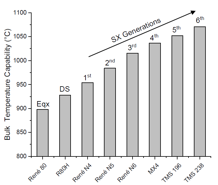

Figure 2. Effect of the main alloying elements in nickel-based superalloys microstructure.
Table 1. The chemical composition (wt.%) for three representative polycrystalline Ni-based superalloys that can withstand service temperatures exceeding 800 °C [19,20].
| Alloy | Cr | Mo | Ti | Nb | W | Co | Al | Ta | B | Hf | C | Zr | Ni |
|---|---|---|---|---|---|---|---|---|---|---|---|---|---|
| CM247 | 8.2 | 0.51 | 0.71 | --- | 9.5 | 9.3 | 5.6 | 3.2 | 0.015 | 1.43 | 0.072 | 0.07 | Bal. |
| IN738LC | 16.0 | 1.75 | 3.4 | 0.9 | 2.6 | 8.5 | 3.4 | 1.75 | 0.01 | --- | 0.11 | 0.05 | Bal. |
| IN939 | 22.4 | --- | 3.7 | 1.0 | 2.0 | 19.0 | 1.9 | 1.4 | 0.01 | --- | 0.15 | 0.1 | Bal. |
2. Casting of IN939 (1970 to1980)
Since the invention of the aircraft gas turbine, there has been an increasing need for materials that can endure elevated temperatures without dropping their strength. This requirement has led to the development of IN939 through investment casting to manufacture blades and nozzle guide vanes in the hot section of aircraft engines and gas turbines [33,34]. The investment casting technique involves creating a wax pattern of the desired blade shape by injecting molten wax into a metallic die. Afterward, the wax mold is coated with ceramic or refractory slurry, solidifying to form a ceramic shell around the wax pattern. Subsequently, the wax is eliminated from the shell through either melting or combustion, creating a hollow void within the shell that precisely replicates the blade shape. Once the refractory shell has been hardened through heating, the actual casting process occurs by filling the shell with the molten alloy. When the molten metal solidifies, the shell is fractured to obtain perfectly shaped components, which are then refined [35,36].
As-cast IN939 exhibits a dendritic microstructure (Figure 3a), which consists of a matrix γ phase along with other precipitated phases such as γ′ particles, MC carbides, and η phase illustrated in Figure 3b. At the interdendritic regions MC carbides, γ/γ′ eutectics, and the η phase platelets are typically found, Figure 3c. The γ′ particles vary in size and shape, such as cuboidal and script-like, appearing both in the dendrite cores and in the interdendritic regions. In these interdendritic areas, with sizes ranging from 0.5 to 1 μm, Figure 3d [37].
Selecting the appropriate temperature for full solution annealing of γ′ needs to consider the segregation tendencies of different alloying elements, particularly Ti and Al, in various regions between dendrite cores and interdendritic areas [39]. These segregations, which occur during non-equilibrium solidification, lead to γ′ phases with variations in chemical composition and, consequently, different solution temperatures. This issue is especially pronounced in cast components with larger cross-sections that solidify with location-dependent rates. During solidification, secondary precipitates are formed along the interdendritic regions due to element partitioning. Besides the commonly observed γ matrix and γ′ phases, the alloy can also contain other phases, e.g., γ-γ′ eutectics, MC carbides, TCP phases, η phase, and borides in different shapes and quantities. These precipitates can impact the solution annealing temperature and create additional challenges when choosing the most suitable heat treatment parameters [3,39].
For IN939 applications like turbine blades, temperature variations are common, with different mechanical properties needed at the aerofoil section and blade root for optimal performance [3]. At the blade root, with the lowest temperature, mechanical properties are mainly influenced by the material’s initial heat treatment, making room temperature tensile properties a good indicator of service performance. In the hotter aerofoil section, typically at 800–900 °C, the microstructure undergoes progressive changes during operation, often exceeding the temperatures used in the material’s final stage of heat treatment. Thus, mechanical properties in this region need to be validated by those extended high-temperature stress rupture testing [3,19].
Delargy et al., in their extensive and pioneer work, examined the mechanical characteristics of IN939 across two, three, and four-stage heat treatment [19]. The main finding was that the best combination of properties of all the treatments examined is obtained by subjecting the material to an overall heat treatment consisting of three stages: 4 h at 1160 °C, 6 h at 1000 °C, and 4 h at 800 °C. The microstructure produced by such a process consists of a duplex distribution of γ′ precipitates. The primary γ′ is about 120 nm in diameter and the secondary γ′ has an average diameter of about 20 nm. At room temperature, the yield strength was 826 MPa, and the ultimate tensile stress was 1004 MPa with 5.1% elongation and 8.8% reduction in area. High-temperature stress rupture properties at 870 and 816 °C were 124 MPa for a lifetime of 11,127 h and 276 MPa for a lifetime of 1725 h, respectively [19].
The conventional investment casting approach for manufacturing IN939 alloy involves a time-dependent solidification process [25]. Undesirable effects such as chemical segregation and microstructural defects are commonly observed due to the non-uniform cooling in the solidification process. In addition, investment casting involves several steps to obtain the precise shape of the final component, reflecting the need for large production duration and high costs [35]. Furthermore, this traditional approach naturally results in material waste due to the removal of material excess in the machining and post-processing since it follows a top-down production route [19,25].
After casting, IN939 undergoes solution treatment followed by aging, from one up to three consecutive cycles, at different temperatures within the γ/γ′ field to optimize its mechanical properties [25]. Typically, the solution treatment ranges from 1120–1160 °C. The temperature used for the solution treatment controls the dissolution of γ′ and affects the size of the γ grains. At aging, the temperature is carried out from 700 °C to 1000 °C. Usually aged in two different temperatures to promote a bi-modal distribution of γ′ precipitation [8,19]. The coarser particles of γ′ precipitate are formed at the higher temperature heat treatment. A finer secondary dispersion of γ′ occurs at lower temperature heat treatment. Figure 4 depicts the microstructure after a four-stage heat treatment. First, the samples were submitted to solution annealing at 1145 °C for 4 h, then three aging cycles, starting at 1000 °C for 4 h, at 850 °C for 16 h, and finally aged at 760 °C for 16 h. [37]. The micro-segregation at the interdendritic regions is less severe but still present, Figure 4a. The size of the carbide and precipitate becomes bigger, in conjunction with the growth of the γ′ precipitates, Figure 4b. Overall, this heat treatment process promotes γ′ precipitation in a spherical morphology, dispersed inside the γ matrix, with the MC carbides at the grain boundary, Figure 4c. It suppresses the incipient melt phases due to the segregation of elements in the cast structure [22,25,37,38]. Under a slightly simplified two-step heat treatment process, the morphology of the γ′ can be tuned into a cuboidal shape, highlighting the imperative role of heat treatment towards microstructure tuning, Figure 4d.
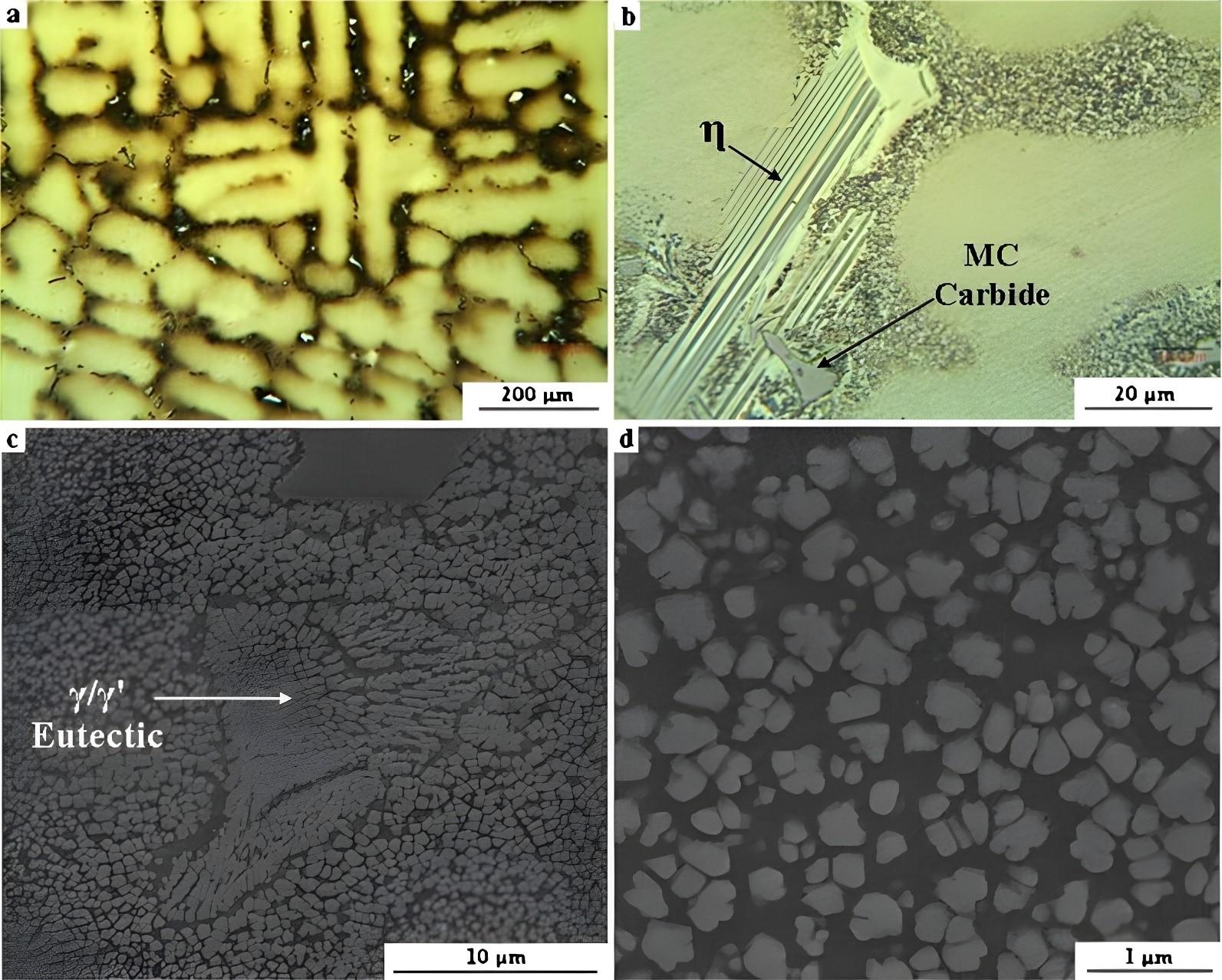
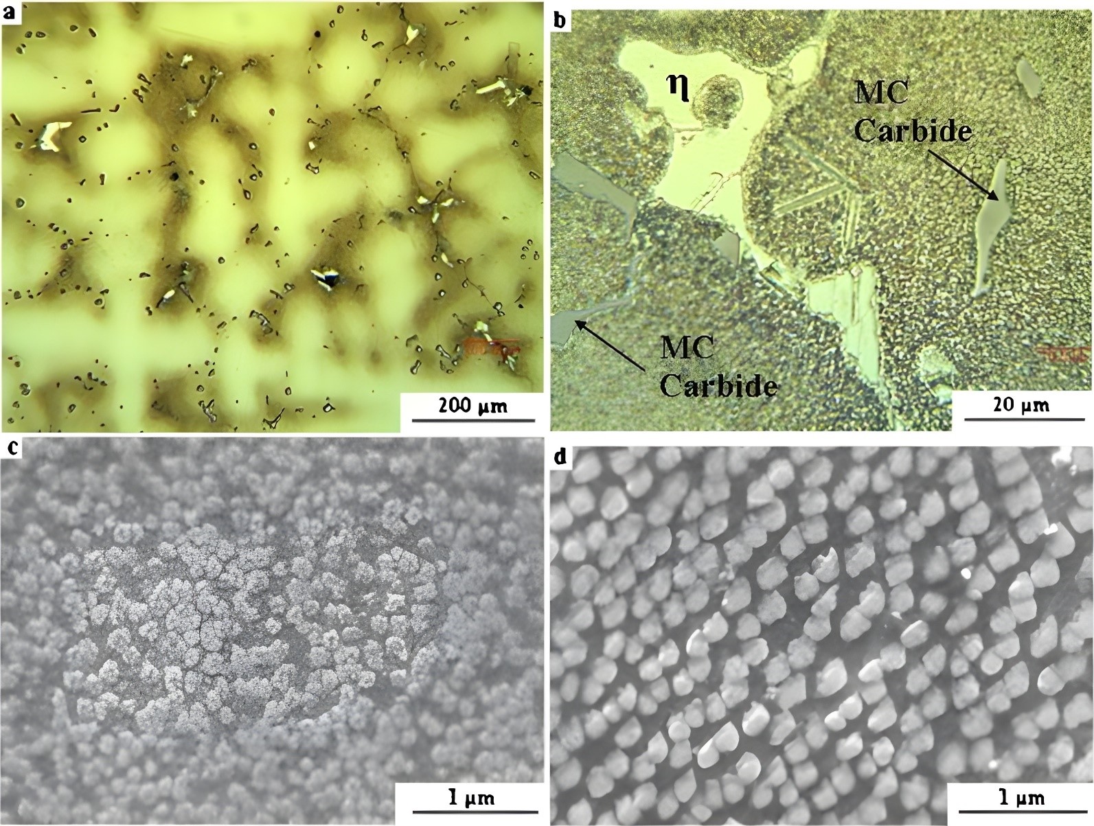
Figure 4. (<b>a</b>–<b>c</b>) The as-cast IN939 microstructures after undergoing the four-stage heat treatment. (<b>d</b>) the microstructure after being furnace cooled following solution annealing and aging at 850 °C for 16 h, showing that the two-step heat treatment turns γ′ precipitation from a spherical shape to a cuboidal shape [37].
3. Oxidation and Microstructure Stability of IN939 (From 1980 to 1990)
IN939 is designed to withstand prolonged exposure to service temperatures up to approximately 850 °C [19]. Despite the superior high-temperature stability of IN939 compared to other metallic materials, the extreme temperatures in the hottest sections of a gas turbine will inevitably impact the microstructure and the mechanical properties [19,40]. One significant mechanism of degradation is oxidation due to long-time high-temperature service exposure of these components [41]. As oxidation progresses, the areas capable of load-bearing decrease, and it may lead to the initiation of fatigue cracks. The oxidized layer does not only reduce the effective load-bearing areas, but it also depletes the γ′ formers underneath, e.g., Al and Ti, which are strong oxide formers. Consequently, the region close to the oxide zone lacks γ′ particles, resulting in a loss of strength. This process of oxidation can locally modify the chemical composition and microstructure, ultimately leading to the failure of the component [42]. Understanding the oxidation behavior of the alloy helps predict the component’s performance and longevity under these conditions. In addition, the knowledge of oxidation behavior supports maintenance schedules and safety protocols, ensuring reliability and safety in critical applications, which will be directly reflected in operational costs [4,43].
The oxidation of IN939 involves the formation of a variety of oxides in a sequential manner [43]. In general, its formation is developed in an oxide scale which comprises different types of oxide species, growing in layers from the surface metal according to exposure to the environmental conditions [43]. In this first stage, NiO oxide and its spinel forms, e.g., Ni (Al, Cr, Co)2O4 start to appear on the material’s outer surface. As oxidation continues, these metastable transition oxides will be replaced by more stable oxides, such as Al2O3 and Cr2O3, following their equilibrium Gibbs free energies [43]. These stable oxides form a protective layer over the surface [4,44]. Then the Al2O3 and Cr2O3 growth achieves a steady state controlled by diffusion [43]. Over these oxide layers, a profile of stress starts to pile up [44]. The origin of such a stress profile is due to the mismatch of the oxide phases and the base metal matrix. They have different lattice spacings and thermal coefficients. As a result, spalling takes place, removing these oxides from the protective outer layer and the base metal. The base metal will then be exposed to the environment, increasing the rate of metal loss. Mainly, the oxidation process will consume elements like Al, Cr, and Ti causing their depletion in the base metal. After a prolonged oxidation time, these elements reach a concentration below a critical threshold and are unable to form the protective layer. The oxidation rate will no longer be under control, leading to what is known as breakaway oxidation [4,44,45].
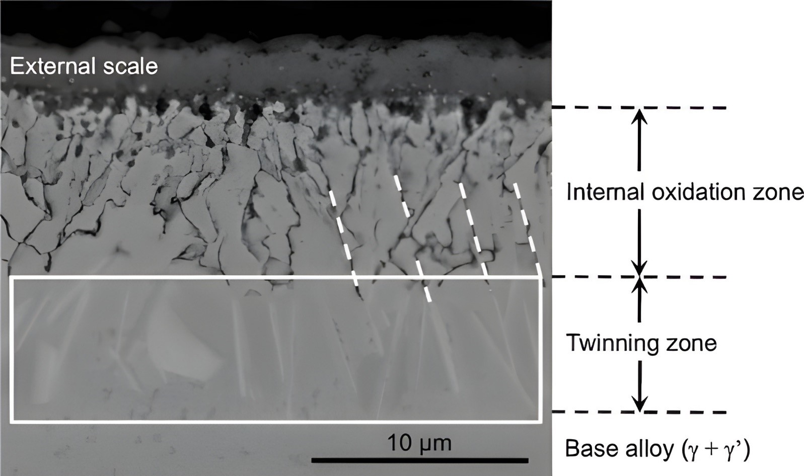
An early study on the oxidation behavior of IN939 examined oxide scale formation at 700, 900, and 1100 °C between 1 to 100 h in air [43]. The composition of the final oxide scale has an outer layer of TiO2 and Cr2O3 and an inner layer of (Ti, Nb, Ta)O2. Other oxide spinel phases such as NiAl2O4 and NiCr2O4 were found in the middle layers. Within the matrix, an internal corrosion zone containing Al2O3 directly above TiN precipitates is also detected [43]. Other studies mentioned that the oxidation resistance of IN939 primarily depends on its Cr content [4]. An external Cr2O3 layer protects from rapid oxidation [4]. However, Cr becomes unstable when the exposure temperature exceeds 1000 °C. At these high temperatures, the external Cr2O3 scale continuously oxidizes into CrO3, which can subsequently transform into a gaseous form leaving the material’s surface by volatilization [46]. Under a combustion environment, besides the outer and inner zones mentioned in the previous studies, a twinning zone depleted of γ′ strengthening precipitates can also occur in IN939 [42,47]. Beneath the internal oxidation zone lies the twinning zone, where numerous grains appear as twins, as shown in the rectangle in Figure 5. Particularly, several internal oxide threads, marked by dotted lines, grow in a specific direction within this zone, maintaining a nearly parallel alignment. Additionally, at the ends of these oxide threads, slab-shaped grains emerge and extend toward the base alloy in the same direction. This suggests a strong correlation between the internal oxides and the formation of these slab-shaped grains [47].
Besides oxidation, nickel-based superalloys also undergo microstructural degradation during prolonged exposure to high temperatures. During the service, the microstructure gradually approaches the equilibrium state [49,50]. Some microstructure transformations include the coarsening of the γ′ particles, M23C6 carbides precipitation along the grain boundaries, decomposition of MC carbides, and the development of TCP phases such as σ [51,52]. These microstructural changes are time-dependent and typically result in a decrease in the material strength and creep resistance causing degradation of the mechanical properties [53,54].
Certain microstructure transformations are irreversible, forbidding component repair, and, in some cases, could result in the rejection of components [41]. Consequently, several studies tried to understand the mechanisms behind these microstructural changes in IN939, since they are crucial for extending the lifespan of the gas turbine vanes [28,40,55,56]. For instance, a study by Footner and Richards reported transformations in the microstructure, such as the coarsening of γ′ particles after 15,000 h at 870 °C and 930 °C [55]. In addition, Delargy and Smith show the presence of the σ phase after examining creep resistance over 10,000 h at 816 °C [40]. Jahangiri and Abedini, in an analysis of service-exposed for 65,000 h of IN939 gas turbine vanes at 1060 °C, inlet temperature, confirmed the presence of a continuous film of M23C6 carbides in the grain boundaries along with the formation of η phase and both were degradation mechanisms in the components [41].
The irreversible microstructural transformations in IN939, such as the coarsening of γ′ particles and the formation of detrimental phases like σ and η phases, significantly impact the material’s mechanical properties and long-term service. These changes, often resulting from prolonged exposure to high temperatures, lead to a decline in mechanical strength.
Under the long-term cyclic oxidation environment, IN939 coated and uncoated variants were analyzed. They report that after 4500 h at 870 °C, the oxide scale comprises an out layer of NiO, an intermediate spinel, and inner Cr2O3 layers [48]. One research utilized vanes made from IN939 that had been in service for an extended period of 65,000 h [4]. These gas turbine vanes serviced at operating temperatures up to 800 °C. The weight loss rate due to oxide scale evolution of three different specimens was examined, namely sample A (as-received, service-exposed at 850 °C for 65,000 h); sample A2 (solution-treated at 1160 °C for 4 h, followed by 850 °C for 16 h aging); and sample A4 (solution-treated at 1160 °C for 4 h, followed by 1000 °C for 6 h, 900 °C for 24 h and 700 °C for 16 h), Figure 6 [4].
At a temperature of 830 °C, as-received (sample A) and one-step aging (sample A2) had a similar oxidation rate, Figure 6a. In contrast, the weight rate loss for the three-step aging (sample A4) was much higher, e.g., −6 vs. −1.5 mg/cm2 after 800 h, when compared to the other two samples. The underlying mechanism is likely to be the presence of internal oxidation, as shown in Figure 7. For samples A and A2, the oxide scales primarily occurred on the surface of the IN939 alloy, and they remained continuous on the surface, Figure 7a,b. However, for the A4 sample, besides the surface oxidation, internal oxidation was detected underneath the oxide scale, Figure 7c,d. It is thus expected that the microstructure of the post-served alloy would have a huge influence on its oxidation performance at this temperature. At a temperature of 930 and 1030 °C, the difference in oxidation properties among the samples are more similar, Figure 7b,c. The as-received sample performed slightly better at 930 °C, but worse at 1030 °C. The chemical analysis of the regions in Fig. 4d reveals distinct compositional differences. Region 1 is characterized by a high oxygen (40.7 wt.%) and chromium (56.7 wt.%) content, with minimal aluminum (0.2 wt.%) and titanium (2.4 wt.%), suggesting the presence of a Cr-rich oxide. In contrast, region 2 exhibits significantly lower oxygen content (3.2 wt.%) and a more balanced elemental distribution, including notable amounts of nickel (52.5 wt.%), cobalt (18.5 wt.%), chromium (13.4 wt.%), aluminum (9.2 wt.%), and titanium (3.2 wt.%). This composition indicates that Region 2 is part of the base alloy matrix, enriched with Ni and Co, while Region 1 represents an oxide layer primarily composed of Cr-oxides [4].
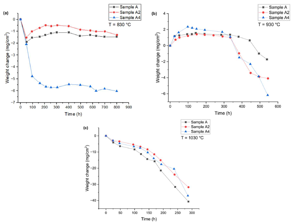
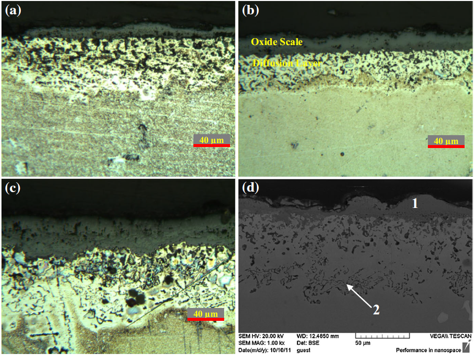
Figure 7. Cross-section Images of the samples after 800-h oxidation at a temperature of 830 °C. (<b>a</b>) sample A, (<b>b</b>) sample A2, (<b>c</b>) and (<b>d</b>) sample A4 under different magnifications, suggesting that the microstructure of the post-served alloy influence its oxidation performance [4].
4. Repair of IN939 (From 1990 to 2010)
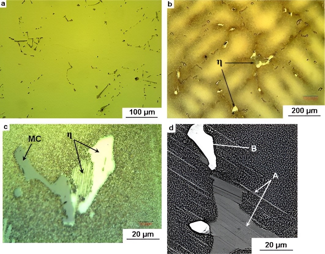
Understanding the microstructural evolution after long-duration services is crucial to designing a suitable repair strategy. Jahangiri et al. studied the microstructure evolution of the airfoil after a 65,000 h operation, Figure 8 [41]. Figure 8a presents the unetched optical microstructure of the outer wall section of the vane, revealing the presence of Chinese script primary MC carbides. The etched optical microstructures of the same sample at varying magnifications are illustrated in Figure 8b,c, showing a dendritic structure in this region. The microstructure consists of the γ matrix along with precipitates such as γ′ particles, MC carbides, and other bright-appearing phases in blocky or platelet forms, identified as η phases. Figure 8d provides a detailed view, highlighting region A (η phase) and region B (MC-type carbide) within the sample [41].
Traditionally, methods such as shot peening, laser peening, and coating have been used to enhance turbine blades fatigue strength and lifespan [57,58,59]. In the event of blade damage, repair techniques like transient liquid phase (TLP) and brazing are deemed suitable methods to mitigate the high replacement costs. Due to the need for shorter turbine blade repair lead time, many studies have investigated the efficiency of remanufacturing these components [60,61]. Traditional fusion welding techniques like shielded metal arc welding (SMAW) or gas metal arc welding (GMAW) are improper for precipitate-strengthening Ni-based superalloys due to potential microstructure disruption and hot cracks caused by γ′ formers [62,63]. In this scenario, TLP bonding, also known as active diffusion bonding, emerged as a practical way of welding materials such as IN939 [64].
TLP is a solid-state joining process used to bond materials, typically metals or alloys, together. In TLP bonding, a thin layer of a specially designed alloy is placed between the surfaces of materials to be bonded. When subjected to elevated temperatures, this intermediate layer melts and forms a liquid phase, facilitating the diffusion of atoms between the coupling surfaces [65,66]. This diffusion allows the formation of strong metallurgical bonds between the materials to be joined. After the bonding process is completed, the liquid phase re-solidifies, resulting in a joint with properties alike, or sometimes even superior to, the base materials. TLP bonding is often used in applications requiring high joint strength, excellent mechanical properties, and good thermal stability [67]. An early study explored TLP bonding in nickel-based heat-resistant alloys MarM-247 and IN939, employing filler metals specifically engineered, the composition was designed with five elements, Co, Cr, Ta, Al, and B. Each was chosen according to their role in the base alloy to be bonded. They were fabricated into flexible foils through rapid solidification processes [67]. It was observed in both superalloys, that the microstructure was almost the same as the base metal, a high bonding pressure of 10 MPa was needed to attain high-stress rupture of 950 MPa, and the IN939 TLP bond was better than the Mar-M247 TLP bond [67].
Aluru et al. [68] conducted different research where they tried to bond IN738 to IN939 by using wide-gap TLP bonding. Their findings revealed that the shear strengths of the joints were primarily influenced by the density of γ′ at the bond centerline [68]. Another investigation was conducted to understand the microstructural development, during solidification and solid-state precipitation, between dissimilar TLP bonding of Inconel 939 and Inconel 625 with a commercial amorphous filler foil Ni-Cr-Fe-Si-B (MBF-15) [69]. Three distinct regions, namely the intermetallic solidification zone (ISZ), adhesive solidification zone (ASZ), and distortion-affected zone (DAZ), were identified within the joint. The ISZ is formed on both sides of the joint, comprising a Ni-rich solid solution phase, with Inconel 939 showing higher microhardness than Inconel 625. Athermal solidification, driven by Cr and B segregation, formed Ni-rich boride, Cr-rich boride, and eutectic-γ phases in the middle ASZ, where the highest microhardness was observed. High Cr in Inconel 939 and Mo and Cr in Inconel 625 caused the precipitation of borides in the DAZ within the base materials, leading to Cr depletion in the matrix. Increasing the holding time from 10 to 40 min maintained the overall joint width but reduced the ASZ width, with isothermal solidification achieved at 30 min and increased solute concentration at the joint centerline with longer holding times [69].
The impact of bonding time on dissimilar joints between IN939 and IN625 superalloys was investigated in the following study using MBF-15 [64]. The examination of the microstructure showed the presence of blocky and needle-like chromium-rich borides in the heat-affected zone (HAZ) of IN939, while the HAZ on the IN625 side was dominated by blocky Cr-Mo-rich borides within the grain boundary. Initially, the width of IN939-HAZ increased with bonding time as a result of boron B diffusion from the filler alloy. However, longer bonding times caused a reduction in IN939-HAZ width due to precipitate dissolution. In contrast, IN625-HAZ width showed a steady increase with bonding time owing to boron diffusion through grain boundaries [64].
Compared to TLP, brazing is a metal-joining process that involves the melting of a filler metal and its distribution by capillary action between two or more close-fitting parts [70]. The filler metal is heated above its melting point and flows into the joint then solidifies to form a strong, sealed joint. Usually, brazing is more cost-effective for repairing gas turbine blades with shallow cracks and large surface areas [70,71,72]. Repair of gas turbines by brazing with different alloys has been extensively studied [70,73,74,75,76,77]. The repair of superficial defects on used blades or vanes is closely related to cost considerations for many end users, leading to increased attention on repair brazing technology [70]. In the repair brazing of superalloys, at least two types of powders are used to enhance the high-temperature strength of the brazed zone. One powder, with a higher melting point, improves the high-temperature properties of the brazed zone, ensuring properties equivalent to or better than the base metal. The other powder, a braze alloy with a lower melting point, offers bonding to the substrate [70]. For repair brazing of IN-939 superalloy, usually Rene 80 nickel-based superalloy powder is chosen as the base powder, and DF3 powder is used as the braze alloy powder [78].
One study examines the vacuum repair brazing of Inconel 939 using various ratios of DF3 and Rene 80 powder mixtures [70]. The main findings were that as the proportion of DF3 in the powder mixture increases, the porosity of the brazed zone decreases, with the lowest porosity achieved using a 50% DF3 and 50% Rene 80 powder mixture. The brazed zone contains at least four phases: Cr borides, sparse carbides, a Ni-rich matrix, and eutectic phases. The carbides primarily come from the Rene 80 powder, as the DF3 braze alloy lacks C. During the early stages of repair brazing, primary Cr borides are formed. The diffusion of nickel from the Rene 80 powder into the molten braze leads to isothermal solidification of the remaining melt. This melt then shifts its composition toward the lowest eutectic temperature, resulting in the formation of the eutectic phase [70].
Another study examined the microstructural evolution of the Inconel 939 joint subjected to diffusion brazing [79] using an amorphous liquated Ni-Cr-Fe-Si-B amorphous foil (MBF20). By melting the filler material and allowing it to flow via capillary attraction, the study showed that isothermal solidification occurred during diffusion brazing at a temperature of 1120 °C for 45 min, which could result in the successful formation of an intermetallic-free centerline consisting of a single-phase γ solid solution. Insufficient bonding time would lead to athermal solidification, resulting in the formation of primary γ and eutectic micro-constituents composed of Ni-rich boride, γ, and Cr-rich boride. Cr-rich boride precipitates were identified in the diffusion-affected zone (DAZ) of the bond, accompanied by Cr depletion in the gamma matrix adjacent to these precipitates. The precipitates decreased in concentration when moving away from the bonding interface [79].
TLP bonding and brazing are key techniques for repairing IN939 superalloy components, particularly in turbine blades subjected to long service times in high-temperature environments. TLP bonding creates strong metallurgical joints through controlled diffusion, maintaining or improving the base material’s properties. Brazing, a cost-effective alternative, uses filler metals to repair surface cracks and defects with minimal disruption. Both methods require careful control of bonding time and filler composition to optimize joint strength and reduce defects, making them essential for extending the lifespan of turbine blades and reducing replacement costs.
5. Additive Manufacturing of IN939 (2010 to Present)
Additive Manufacturing (AM) has been gaining popularity in recent years as a method to manufacture gas turbine components due to the efficiency of the process, and the ability to produce complex designs for improved performance, which would be difficult, time-consuming, and expensive to produce using conventional techniques [80,81,82,83]. This is becoming increasingly important with the hollow structures and cooling channels present in modern turbine components [27]. Among the additive manufacturing techniques, laser power bed fusion (LPBF) or selective laser melting (SLM) is arguably the most widely adopted approach to process the IN939 parts due to its high fabrication accuracy with minimal need for post-processing [84]. In this technique, a laser scans selectively over alloyed powder material, melting and fusing it layer by layer till the entire part is produced.
The quality and performance of AM-built components are significantly impacted by the precise control of manufacturing parameters [26]. The key parameters in the LPBF process are the laser power, scanning speed, hatch spacing, and layer thickness [25,26,85]. Laser power is the primary source of energy transfer in the LPBF system for processing the alloyed powder by melting it in a consistent and controlled manner to ensure the densification of bulk parts. The scanning speed then determines how fast the laser beam moves across the powder bed surface, setting the build rate and influencing the duration each part is exposed to the laser, which affects the energy available for melting. Hatch spacing, defined as the spacing between consecutive laser passes, controls how the powder bed surface is heated—too large a distance may lead to incomplete contact between molten areas, while a smaller distance can result in excessive energy input. Lastly, the powder layer thickness defines the height of each layer to be melted by the laser beam, directly impacting the build rate and, consequently, the total manufacturing time for each component [25,26,85].
The process parameters define the microstructure of AM-built parts. This microstructure differs substantially from those produced conventionally by casting [25]. The rapid cooling associated with this process generates significant temperature gradients, resulting in large residual stresses within the solidified material [25,86]. Furthermore, quick cooling often kinetically suppresses the formation of precipitates. Grain growth occurs epitaxially across the build layers through partial remelting of preceding layers, resulting in an elongated columnar structure [87]. Once the heat treatment process is applied, this structure could be transformed as a result of recrystallization. This phenomenon occurs due to the high level of strain-induced defects present in the sample caused by thermal gradients, leading to this grain growth along with the build direction [88]. Studies in the last few years have indicated that utilizing AM can be a feasible method for enhancing mechanical properties at elevated temperatures, fatigue, and creep resistances, as well as optimizing the microstructure formation of nickel-based superalloys [25,26,85,86]. This scenario triggered research interest in using the LPBF manufacturing route for producing IN939 parts.
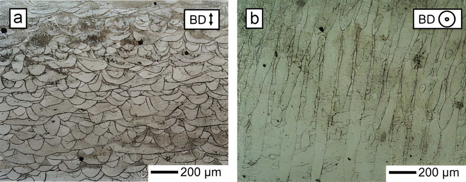
An initial study of LPBF IN939 material performed by Kanagrajah et al. investigated how microstructure and temperature affected the mechanical properties under static and cyclic loading and compared the results to the conventional cast alloy [89]. It was revealed that LPBF created a distinct microstructure with fine columnar grains and micro-scaled substructures across multiple layers in Figure 9. Arch-shaped lines corresponding to the boundaries of the melt pool during processing were visible in Figure 9a. Perpendicular to the build direction, these features appeared elongated, as the melt pool follows the scanning direction of the laser energy source (Figure 9b).
Despite going through two-stage heat treatment, the LPBF-built IN939 specimen still had a significantly smaller grain (about 60 µm in width) in comparison to the cast alloy (around 300 µm). Under monotonic loading, the as-built LPBF samples showed higher ductility (15% horizontal and 25% vertical) than their as-cast counterpart (3%), regardless of the build direction. At the same time, the LPBF sample’s strength is also higher than the as-cast specimen, i.e., 800 vs. 600 MPa for yield strength, and 900 MPa vs 800 MPa for ultimate tensile strength. After heat treatment, the strength of the LPBF sample is still higher, but the ductility drops significantly to less than 3% for standard two-step solution and aging heat treatments [89].
Under cyclic loading, as-built LPBF samples demonstrated superior performance to the as-cast material at room temperature. They could sustain 4702 cycles, instead of 313 cycles for the as-cast specimens. This higher number of cycles obtained by LPBF was attributed to lower energy dissipation per cycle due to their distinct microstructures. However, at 750 °C, the cyclic performance decreased for both, with the LPBF sample, having a worse performance, i.e., 209 vs. 230 cycles. This sharp decrease is likely associated with the rapid formation of precipitates leading to embrittlement. After aging treated, fatigue lives for both LPBF and cast specimens decrease at room temperature and 750 °C. The values were for LPBF-aged 1598 cycles at room temperature and 73 cycles at 750 °C. In the case of cast-aged samples 2677 cycles at room temperature and 272 cycles at 750 °C [89].
Kubӗna et al. [90] studied the fatigue behavior of LPBF IN939 specimens in parallel and perpendicular build directions at 800 °C and 900 °C after a three-step heat treatment (solutionizing at 1160 °C for 4 h, followed by aging at 1000 °C for 6 h and 800 °C for 4 h) and compared them to as-cast specimens. Under cyclic loading, strain amplitude increased uniformly, but different material variants failed after varying cycles, with stress amplitudes differing at the same strain levels. LPBF specimens built parallel to the loading axis exhibited higher cumulative plastic deformation, increasing with temperature, due to a strong <001> texture, which resulted in the lowest elastic modulus but highest flow stress. Cyclic stress-strain analysis confirmed this, with LPBF parallel specimens showing the lowest cyclic elastic modulus (130 GPa at 800 °C; 108 GPa at 900 °C), while the cast material had the highest (168 GPa at 800 °C; 161 GPa at 900 °C), consistent with single-crystal <001> data. Microstructural evolution also differed, with cast specimens forming persistent slip bands (SBs), which promote crack initiation and early growth, explaining their lower cumulative plastic deformation [90]. A following study was performed by Babinský et al. [91] compared the room-temperature low-cycle fatigue life of LPBF samples in as-built and aged conditions (same heat treatment), printed in horizontal and vertical directions concerning the loading axis, to cast-aged samples. LPBF samples showed superior fatigue performance than the cast ones. In cast samples, stress amplitude increased significantly with decreasing fatigue life, reaching 1093 MPa at 89 cycles. LPBF as-built samples (both vertical and horizontal) had lower stress amplitudes, indicating better fatigue resistance. Aged LPBF samples showed improved fatigue life at 0.35% strain amplitude, with LPBF horizontal-aged achieving the highest fatigue life (90,915 cycles). Plastic strain amplitude increased with higher strain amplitudes and lower fatigue life, with the highest value (0.4802%) recorded for LPBF horizontal as-built at 1% strain amplitude. Heat-treated LPBF samples had higher strength but reduced plasticity, while as-built samples were more resistant to cyclic plastic deformation [91].
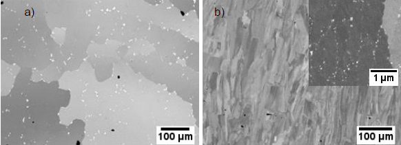
In a separate study, Philpott et al. confirmed that the starting microstructure of IN939 produced by LPBF differs significantly from the as-cast one, Figure 10 [92]. The as-cast samples have large equiaxed grains with uniformly distributed carbides. As for the LPBF-built specimen, its grains are mostly columnar, with smaller carbides mostly decorated at the grain boundaries. It is because of their microstructural difference in the as-built state, that they have distinct responses to heat treatments. After heat treatment, besides the differences in grain structure, the as-cast material experienced dissolution for some carbides, followed by the formation and coarsening of new carbides, while the grain structure remained stable. In contrast, LPBF-built specimens only had carbide coarsening, which happened quickly during the first heat treatment step, these MC-type carbides are typically enriched in Ti. In addition, the LPBF microstructure showed recrystallization, with the grain structure transitioning from stressed, elongated grains to larger equiaxed grains. Moreover, the size and distribution of the MC-type carbides are different for the LPBF and cast samples. Under aging conditions, the as-cast sample’s carbide is about 5 µm in size with a 10 µm distance between each carbide. However, the LPBF material presented very small carbides, around 0.5 µm size, and were closely distributed, less than 1 µm apart. Despite the differences related to grain and carbides, it is found that the γ′ precipitates in both materials were similar after a three-step heat treatment [92].
Marchese et al. studied how process parameters influence the densification of LPBF-built IN939 alloy and its microstructure [93]. By optimizing the process parameters, conditions were identified that reduce porosity and cracking. With a laser spot size diameter of about 50 μm, and a fixed laser power of 95 W, a powder layer thickness of 20 μm, the ideal hatching distance was found to be 0.03 mm. Smaller hatching distances caused melt pool instability and keyhole formation, while larger distances led to incomplete fusion due to insufficient overlap. A scanning speed of 1000 mm/s effectively reduced the porosity but increased crack formation due to high energy input. In opposition, increasing the scanning speed to 1800 mm/s reduced the cracking formation but increased the residual porosity due to lower energy input. Thus, there is an inverse relationship between the number density of cracks and gas pores. Two representative samples were highlighted within the study to illustrate this point: one with a scanning speed of 1800 mm/s and a hatching distance of 0.03 mm, which had the lowest cracking density; and another with a scanning speed of 1000 mm/s and the same hatching distance, which had the lowest residual porosity but higher cracking density. Regarding the microstructure, the analysis showed elongated grains along the building direction with a strong <001> texture. Within the grains, dendritic and cellular structures with sub-micrometric phases were observed, primarily along grain boundaries and interdendritic areas. They suggested that the rapid cooling rates of the LPBF process were not sufficient to completely prevent these phase formations [93].
Doğu et al. [94] investigated different scanning strategies and material properties of IN939 processed via LPBF. They tested alternating bi-directional scanning with 0°, 45°, 67°, and 90° rotations and chessboard scanning with 67° and 90° rotations. The 45° and 67° bi-directional scans achieved the highest relative density, while the 0° and chessboard with 67° scans had the highest porosity. Cracks were observed as solidification, solid-state, and oxide-induced (Al2O3), with the 0° scan showing the most cracking and highest residual stress. The 67° scan exhibited the lowest residual stress in the XZ plane. Microstructural analysis showed strong cube textures in 0° and 90° scans, while 45° and 67° scans had weaker textures. Chessboard scanning led to rougher surfaces. Mechanically, 0° and 90° bi-directional scans induced high thermal gradients and residual stresses, with the 0° scan reaching 738.3 MPa (XZ) and 581.6 MPa (XY). The 67° scan had the lowest residual stress (542.6 MPa in XZ, 443.9 MPa in XY) due to improved thermal uniformity and recrystallization. Chessboard scanning reduced thermal gradients but had measurement accuracy limitations, with the lowest residual stress (408.4 MPa) found in the XY plane of the chessboard 67° sample [94].
Banoth et al. investigated the creep behavior of LPBF-built IN939 processed along the build direction and compared it with a conventional cast alloy [95]. In the as-built condition, the LPBF-built IN939 showed a high dislocation density due to the larger thermal gradient experienced, making post-heat treatment necessary to achieve the desired mechanical properties. Two heat treatment methods were applied: a lower temperature treatment (LTH: solution treatment at 1160 °C/4 h + aging at 850 °C/16 h) and a higher temperature treatment (HTH: solution treatment at 1240 °C/6 h + aging at 850 °C/16 h). Creep tests at 816 °C/250 MPa revealed that LPBF specimens in as-built and LTH conditions had poor creep life (66 and 203 h, respectively) but good elongation (3.0 and 2.7%, respectively). The short creep life of the as-built specimen was attributed to high dislocation density and small recrystallized grains formed between columnar grains. In the LTH-treated specimen, the formation of ƞ phase at the grain boundary and small recrystallized grains (27 µm) led to poor creep life, Figure 11a. However, the HTH-treated specimens showed a 2.7-times longer creep life (554 h) attributed to the presence of larger recrystallized grains (50 µm) with low dislocation density, improved columnar grain morphology. They increased γ′ precipitates size (53–132 nm) over the creep test, Figure 11b. The cast LTH specimens demonstrated a much longer creep life (931 h) compared to LPBF specimens, and this performance was due to coarser grains (200 µm) with low dislocation density, the γ′ precipitate coarsening during the creep test, and the presence of M23C6 small carbides at grain boundaries, which also contributed to a lower creep strain rate, Figure 11c [95].
Malý et al. explored the effect of preheating the powder bed, ranging from room temperature to 400 °C, on the residual stress (RS), microstructure, and mechanical properties in bridged-shaped LPBF-built IN939 [96]. High-temperature preheating (at 400 °C) led to increased RS reflected in distortion percent, which increased by 16.2% compared to room temperature, and the maximum measured distortion was 0.028 mm. This increase in RS is likely attributed to the γ′ precipitation during the high-temperature fabrication. Regarding the microstructure, a notable change was the size and frequency of the MC-type carbide phase increased with higher preheating temperatures from 0.061 µm at room temperature followed by 0.086 µm at 200 °C and reached 0.105 µm at 400 °C. Due to the microstructural changes, the tensile strength showed a monotonous increment when tested at room temperature. Specimen with no preheating had the lowest yield strength of 800 MPa, while the specimen with a 400 °C preheating had a yield strength of 1000 MPa instead. The ductility, however, had a reverse trend, with corresponding values of 30 and 30% respectively. This study concluded that preheating caused a larger melt pool, widened columnar grains, and promoted the precipitation of the MC-type carbide phase [96].
Recently, from 2022 until the current period, studies conducted about the processing of LPBF-built IN939 are concerned with cracking mitigation, heat treatment, oxidation, and wear mechanisms [84,86,97,98,99,100,101,102]. Cracking is a serious issue in AM, which affects a wide range of alloy systems [103,104,105,106]. On IN939, Zhang et al. investigated the production of crack-free IN939 parts with different Si additions [97]. The main findings were that specimens of IN939 with standard composition displayed numerous solidification cracks along the build direction. The incorporation of additional 1.5 wt.% and 3.0 wt.% Si decreased the crack density, resulting in crack-free areas. It was noted that Si changed the crystallographic orientation and the average columnar grain width besides minimizing the crack density. With the addition of 1.5 wt.% Si, the primary dendritic arm spacing increases by over 50%, indicating a notable reduction in the cooling rate. In addition, Si increased the number of precipitates enriched in Ti, Si, and Nb. The research proposed that solidification cracking is the primary cracking mode in LPBF IN939 parts and that the addition of Si significantly reduces the tendency for this cracking type [97].
Hu et al. evaluated the possibility of reducing the cracking and porosity in LPBF IN939 parts through a layer-wise remelting strategy [98]. It was observed that remelting impacted the porosity by changing the depth of the remelted pool. When the depth of the remelted pool matched that of the initial melt pool, Marangoni convection helped expel pores from the melt layer. This process reduced the porosity from 0.13% in the initial melt sample to 0.05% in the remelted sample. Remelting also decreased the number of large pores (greater than 30 μm), with most remaining pores being around 10 μm. Relative to the original single-scan-per-layer sample (laser power: 125 W, scanning speed: 1000 mm/s), employing remelting processing with a laser power of 125 W and a scanning speed of 1250 mm/s, led to an 85% reduction in crack density (from 0.13 mm/mm2 to 0.02 mm/mm2) and a significant 60% drop in porosity (from 0.15% to 0.06%). Regarding the mechanical properties, it was observed that the original samples had an ultimate tensile strength and elongation of 1061.6 MPa and 26.5%, and the remelted samples showed enhanced properties of 1151.7 MPa and 29.1% at room temperature. This improvement was attributed to the substantial reduction in crack density and porosity achieved through remelting [98].
Tegoklu et al. [107] investigated the effects of incorporating transition metal diborides into IN939 processed via LPBF to enhance mechanical properties and eliminate cracking. Their study demonstrated that the addition of TiB2 nanoparticles inhibited grain growth during solidification, resulting in a significantly finer grain structure compared to pure IN939. This grain refinement played a key role in suppressing cracks under optimized LPBF conditions. The reinforced IN939+TiB2 composite exhibited nearly double the YS and UTS comparison to undoped IN939 while maintaining good ductility (13–15% tensile elongation). Furthermore, the composite retained superior mechanical performance at elevated temperatures (800–850 °C) compared to other additively manufactured and cast samples. The enhanced strength of IN939+TiB2 was attributed to multiple strengthening mechanisms, namely grain boundary, solid solution, thermal expansion mismatch, dispersion, and compositional microsegregation strengthening mechanisms [107].
For the heat treatment of LBPF-built IN939 parts, the main studies focused on the impact of the building direction, appropriate duration, and temperature of the heat treatment, on the final part’s mechanical properties. Kumar et al. started by investigating the effect of heat treatment—solution annealing at 1190 °C for 4 h and double-aged at 1000 °C for 6 h and 800 °C for 4 h followed by fast argon cooling—on microstructure and mechanical properties in crack-free LPBF IN939 samples [84]. The as-built alloy showed a cellular structure with nanosized (60–80 nm) intragranular MC–type carbides. After being heat-treated, the microstructure displayed an equiaxed grain morphology with a <001> crystallographic texture. Concerning the tensile behavior, the transverse direction, both in its as-built state and after undergoing heat treatment, exhibited excellent performance at room temperature, with ultimate tensile strengths of 1099 MPa and 1073 MPa with elongation of 18 and 26%, respectively. Moreover, the heat-treated specimens in the transverse direction were tested at 816 °C and 870 °C and displayed ultimate tensile strengths of 856 MPa and 616 MPa with elongation of 5 and 4%, respectively [84].
A following study performed by Doğu et al. analyzed the impact of different solution heat treatment temperatures (1120, 1160, 1200, and 1240 °C) in the microstructure and texture of LPBF-built IN939 specimens [100]. For solution heat treatment with a temperature from 1120 to 1240 °C, no obvious change in the grain morphology was detected. At 1240 °C, obvious recrystallization occurred and only equiaxed grains around 32 µm were present in the specimen. The texture analysis revealed that both conditions, as-built and solution heat-treated, exhibited a preferred <001> orientation parallel to the building direction. This effect was pronounced as the solution temperature increased. The samples started showing the first recrystallized grains after undergoing solution heat treatment at 1160 °C. The fraction of recrystallized grains increased according to the solution heat temperature, ranging from 0.55 (as-built at room temperature) to 0.97 (at 1240 °C). Authors attributed that the recrystallization was influenced by the size and distribution of TCP phases and MC-type carbides, which restricted grain growth. In addition, under all solution heat treatment conditions resulted in the formation of a significant quantity of nano-sized spherical-like γ′ precipitates, ranging from 35 nm at 1120 °C to 40 nm at 1240 °C in the matrix [100].
These studies in heat treatment have observed the absence of γ′ precipitates in the microstructure of LPBF-built IN939 in their initial as-built state. This absence is attributed to the rapid cooling rates during the LPBF process, which prevents the diffusion-driven precipitation reaction. So, as a consequence, this has led to the suggestion that full-solution heat treatments may not be required for LPBF-processed parts. Shaikh et al. investigated the need for solution treatment of LPBF IN939 in the following heat treatment conditions—solution treatment at 1190 °C for 4 h followed by two-step aging at 1000 °C for 6 h and 700 °C for 16 h, compared to direct two-step aging without prior solution treatment [86]. Despite the absence of γ′ precipitates in as-built condition, platelet-shaped precipitates measuring 0.5 µm, identified as the η phase, were observed in the interdendritic regions. The η phase grew rapidly during the aging cycles, leading to a reduction in ductility at room temperature. Specifically, the solution-treated and aged samples exhibited an ultimate tensile strength of 1429 MPa and an elongation to fracture of 6.4%, whereas the directly aged samples showed an ultimate tensile strength of 1214 MPa and an elongation to fracture of 4.6%. The study suggested that while solution treatment may not be necessary to dissolve γ′, it is still essential for achieving a microstructure free from η phase [86].
Concerning the oxidation behavior, Visibile et al. performed a work comparing as-cast IN939 with LPBF-built IN939 in both as-built and heat-treated conditions—solution treatment at 1160 °C for 168 h followed by one-step aging at 800 °C for 24 h [101]. All samples were exposed under the same oxidizing conditions at 900 °C in dry air for 168 h. The study demonstrated that the oxidation rates of LPBF IN939 as-built in both conditions—parallel and perpendicular to the building direction—are similar to the IN939 as-cast manufactured—Figure 12. The observed mass gain of approximately 0.8 mg⋅cm−2 aligned well with the existing literature. For instance, Abedini et al. [4] reported a mass gain of about 1 mg⋅cm−2 after 168 h at 930 °C, while Lee et al. [48] noted a mass gain of 0.6 mg⋅cm−2 after 75 h at 870 °C. Additionally, the AM material shows some spallation of the oxide layer.
Similar behavior in the internal oxidation zone comprised of Al2O3 was observed in LPBF and as-cast IN939. In contrast, the internal nitridation zone of LPBF-built IN939 contained AlN and TiN along the depth profile from the surface to the bulk metal, while only TiN was found in the as-cast condition and more localized at grain boundaries. These variations were attributed to the finer grain size (60–80 µm) and dendritic cellular structure of the LPBF as-built samples compared to the coarser grains (100–300 µm) in the as-cast condition. Additionally, heat treatment improved the oxide scale adhesion in the LPBF IN939 by coarsening the grains, resulting in an internal nitridation zone similar to the as-cast material [101].
Karabulut et al. investigated the hardness and high-temperature wear behavior of as-cast IN939 in comparison to the LPBF IN939 as-built and heat-treated—solution treatment at 1160 °C for 4 h followed by one-step aging at 850 °C for 16 h [102]. The study revealed that the manufactured route significantly impacted the microstructure and hardness of IN939. Cast samples exhibited coarse, equiaxed grains with discrete carbides, while LPBF-produced samples displayed fine columnar grains, a supersaturated matrix, and Laves phases. Microhardness tests showed that the cast sample had a hardness of 350 HV, while the LPBF-built and heat-treated samples measured 457 HV and 466 HV, respectively. Friction tests indicated that the coefficient of friction values for as-cast IN939 increased with temperature ranging from 0.281 at room temperature to 0.458 at 600 °C, whereas LPBF IN939 as-built and heat-treated showed a gradual decrease ranging from 0.355 and 0.430 at room temperature to 0.428 and 0.373 at 600 °C, respectively. The authors explained that different mechanisms played a role in the wear resistance of IN939—Figure 13.

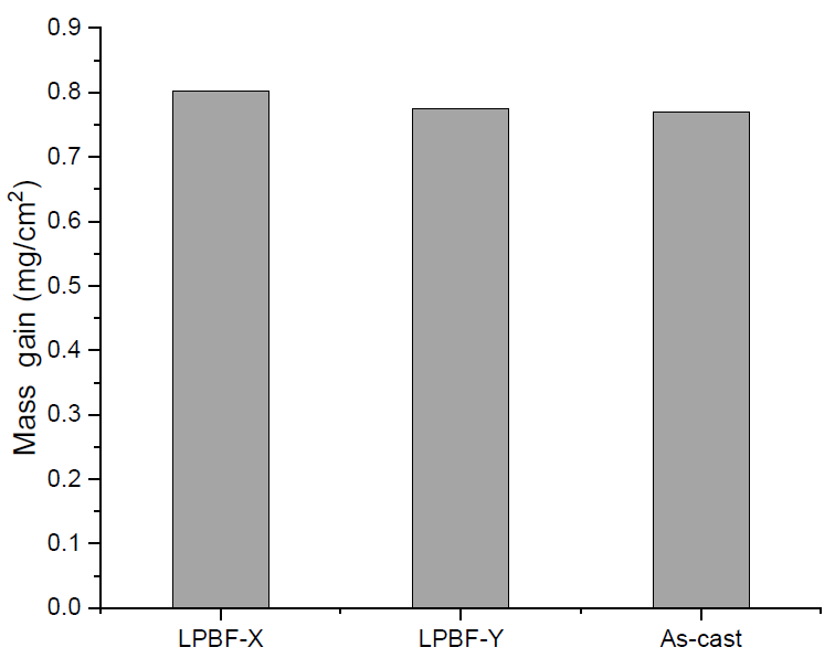
Figure 12. The mass gain after 168 h of exposure under dry conditions for IN939 LPBF in both directions X and Y and as-cast, indicating that the oxidation rates of the as-built in both conditions—parallel and perpendicular to the building direction—are similar to that of the as-cast IN939. Modify from reference [101].
The wear surfaces revealed that specimens displayed irregular and distinct wear damage at 500 °C and 600 °C. At 500 °C, delamination and spalling were observed, while oxidative wear is dominant at 600 °C. In IN939 as-cast the width of the wear marks was larger at room temperature as well as at elevated temperatures compared to the LPBF-built and heat-treated specimens. The wear surface of the casting sample exhibited differences from the LPBF-built and heat-treated samples at room temperature and showed visible damage. Abrasive wear was the primary wear mechanism in the casting sample, while the other two samples displayed a combination of abrasive wear and plastic deformation damage. There was a similarity in the wear mechanisms observed in the test samples at both 500 °C and 600 °C. In all samples, the main wear mechanisms were adhesive wear, delamination, and oxidative wear. These images revealed an increase in oxidative wear at 600 °C, with the wear surfaces showing a more roughened texture. Overall, abrasive wear was predominant in the cast samples at all temperatures (Figure 13a–c), while IN939 LPBF as-built and heat-treated transitioned from abrasive wear at room temperature to adhesive wear, delamination, and oxidative wear at higher temperatures (Figure 13d–i) [102].
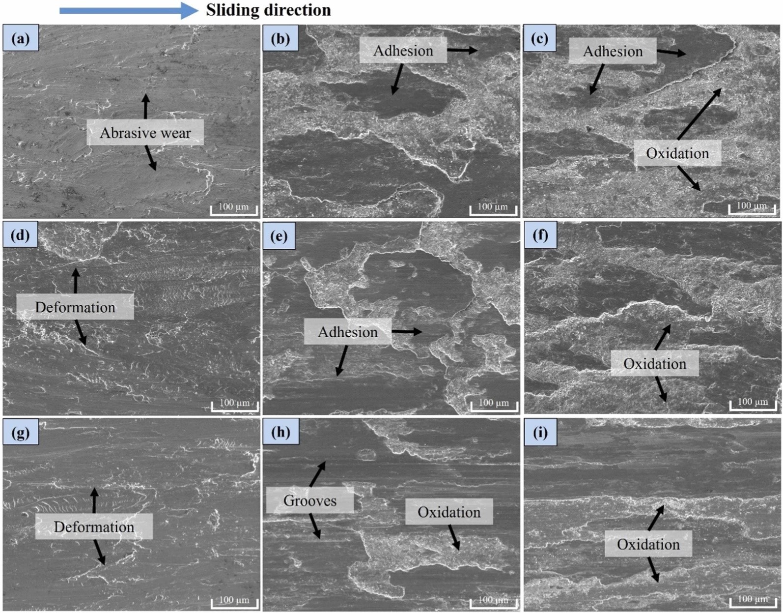
6. Current Challenges
The adoption of LPBF for IN939 manufacturing presents several challenges. A key issue is the lack of standardized processing parameters. There is no consensus on the optimal setup to achieve the desired material properties, as parameter selection is typically based on a broad range of volumetric energy densities that require further refinement. Additionally, rapid solidification during LPBF leads to significant microstructural changes, including anisotropy, grain refinement, and unexpected phase formations that differ from conventionally processed alloys. These microstructural variations must be carefully controlled or mitigated through the development of new processing techniques or post-treatment strategies to enhance overall alloy performance. Residual stress and cracking also pose major concerns due to the high thermal gradients inherent in the LPBF process, potentially compromising mechanical integrity. Various strategies, such as silicon additions, remelting, and ceramic reinforcements, have been explored to address these issues, but they often introduce trade-offs in mechanical properties or remain untested under real operating conditions. Furthermore, the oxidation behavior and wear resistance of additively manufactured IN939 require further investigation to ensure long-term stability in high-temperature environments. Overcoming these challenges is essential for unlocking the full potential of AM-fabricated IN939 components in high-performance industrial applications.
7. Conclusions
Additive manufacturing of IN939, specifically through laser power bed fusion technique, presented a promising route for fabricating components for high-temperature operation with enhanced characteristic performance over service. LPBF allows, beyond the near-net-shape approach in geometry, the precise control of microstructure, resulting in components with improved mechanical properties, such as higher strength, good performances in fatigue and creep life span, as well as oxidation and wear behaviors. The distinctive microstructure formed during LPBF, characterized by fine columnar grains and substructures, can be further optimized through tailored heat treatments, which refine grain sizes and precipitate distributions. Moreover, recent studies have shown ways to overcome defects, such as cracking and porosity, demonstrating the potential of LPBF to produce crack-free, dense parts with excellent mechanical properties. As research on IN939 LPBF advances, discoveries in the area will become essential in developing next-generation high-performance components for advanced turbines that can withstand the rigorous demands of modern engines.
Author Contributions
S.D.L.M., V.S., D.W., S.R.N., D.L., S.W., C.K.N., W.G., P.W., Z.S. and Z.D. contributed equally to this work. All authors participated in conceptualizing the review, conducting literature research, analyzing key findings, and drafting the manuscript. S.D.L.M., Z.S. and Z.D. coordinated the overall structure and provided critical revisions. V.S., D.W., S.R.N., D.L., S.W., C.K.N. and P.W. contributed to data collection, figure preparation, and technical discussions. W.G. provided additional insights and cross-referenced relevant studies. Z.S. and Z.D. supervised the research and finalized the manuscript.
Ethics Statement
Not applicable.
Informed Consent Statement
Data Availability Statement
Not applicable.
Funding
Declaration of Competing Interest
The authors declare that they have no known competing financial interests or personal relationships that could have appeared to influence the work reported in this paper.
References
1.
Betteridge W, Shaw SWK. Development of superalloys. Mater. Sci. Technol. 1987, 3, 682–694. doi:10.1179/mst.1987.3.9.682.[Google Scholar]
2.
Pollock TM, Tin S. Nickel-based superalloys for advanced turbine engines: Chemistry, microstructure, and properties. J. Propuls. Power 2006, 22, 361–374. doi:10.2514/1.18239.[Google Scholar]
3.
Reed RC. The Superalloys: Fundamentals and Applications; Cambridge University Press: Cambridge, UK, 2006. doi:10.1017/CBO9780511541285.
4.
Abedini M, Jahangiri MR, Karimi P. Oxidation and Hot Corrosion Behaviors of Service-Exposed and Heat-Treated Gas Turbine Vanes Made of IN939 Alloy. Oxid. Met. 2018, 90, 469–484. doi:10.1007/s11085-018-9847-4.[Google Scholar]
5.
Gleeson B, Harper MA. The Long-Term, Cyclic-Oxidation Behavior of Selected Chromia-Forming Alloys. Oxid. Met. 1998, 49, 373–399. doi:10.1023/A:1018874206733.[Google Scholar]
6.
Callister DG, Rethwisch WD. Materials Science and Engineering; Wiley: Hoboken, NJ, USA, 2018.
7.
Murakumo T, Kobayashi T, Koizumi Y, Harada H. Creep behaviour of Ni-base single-crystal superalloys with various γ′ volume fraction. Acta Mater. 2004, 52, 3737–3744. doi:10.1016/j.actamat.2004.04.028.[Google Scholar]
8.
Prasad NE, Wanhill RJH. Aerospace Materials and Material Technologies Volume 1: Aerospace Materials; Springer: Singapore, 2017. doi:10.1007/978-981-10-2134-3.
9.
Robert S. Saga of gas turbine materials. Adv. Mater. Process. 2004, 5, 29–33. [Google Scholar]
10.
Thellaputta GR, Chandra PS, Rao CSP. Machinability of Nickel Based Superalloys: A Review. Mater. Today Proc. 2017, 4, 3712–3721. doi:10.1016/j.matpr.2017.02.266.[Google Scholar]
11.
Darolia R. Development of strong, oxidation and corrosion resistant nickel-based superalloys: Critical review of challenges, progress and prospects. Int. Mater. Rev. 2019, 64, 355–380. doi:10.1080/09506608.2018.1516713.[Google Scholar]
12.
Kawagishi K, Sato A, Harada H, Yeh AC, Koizumi Y, Kobayashi T. Oxidation resistant Ru containing Ni base single crystal superalloys. Mater. Sci. Technol. 2009, 25, 271–275. doi:10.1179/174328408X361517.[Google Scholar]
13.
Kawagishi K, Yeh A, Yokokawa T, Kobayashi T, Koizumi Y, Harada H. Development of an Oxidation-Resistant High-Strength Sixth-Generation Single-Crystal Superalloy TMS-238. In Proceedings of the Superalloys 2012, Hoboken, NJ, USA, 9–13 September 2012; pp. 1–10. doi:10.1002/9781118516430.ch21.
14.
Jena AK, Chaturvedi MC. The role of alloying elements in the design of nickel-base superalloys. J. Mater. Sci. 1984, 19, 3121–3139. doi:10.1007/BF00549796.[Google Scholar]
15.
Xu J, Gruber H, Peng RL, Moverare J. A novel γ′-strengthened nickel-based superalloy for laser powder bed fusion. Materials 2020, 13, 4930. doi:10.3390/ma13214930.[Google Scholar]
16.
Donachie MJ, Donachie S. Superalloys: A Technical Guide, 2nd ed.; ASM International: Materials Park, OH, USA, 2002.
17.
Choi BG, Kim IS, Kim DH, Seo SM, Jo CY. ETA Phase Formation During Thermal Exposure and Its Effect on Mechanical Properties in Ni-Base Superalloy GTD 111. Mater. Sci. Forum 2004, 449–452, 821–824. [Google Scholar]
18.
Bouse GK. ETA (77) and Platelet Phases in Investment Cast Superalloys; National Technical Information Service: Springfield, VA, USA, 1984.
19.
Delargy KM, Shaw SWK, Smith GDW. Effects of heat treatment on mechanical properties of high-chromium nickel-base superalloy IN 939. Mater. Sci. Technol. 1986, 2, 1031–1036. doi:10.1179/mst.1986.2.10.1031.[Google Scholar]
20.
Satyanarayana DVV, Omprakash CM, Jagadeesan B, Das N. Effect of section thickness on creep and stress rupture behaviour of DS CM247 nickel base superalloy. Mater. High Temp. 2008, 25, 17–26. doi:10.3184/096034007X300485.[Google Scholar]
21.
Jahangiri M. Influence of Cooling Rate During Solidification on Microstructural Features and γ′ Size and Morphology in Cast IN939 Superalloy. Int. J. Metalcast. 2023, 18, 2357–2379. doi:10.1007/s40962-023-01183-7.[Google Scholar]
22.
Formenti A, Eliasson A, Mitchell A, Fredriksson H. Solidification Sequence and Carbide Precipitation in Ni-Base Superalloys IN718, IN625 and IN939. Mater. Res. Soc. Symp. Proc. 2005, 842, S5.7. doi:10.1557/PROC-842-S5.7.[Google Scholar]
23.
Formenti A, Eliasson A, Mitchell A, Fredriksson H. On the Dendritic Growth and Microsegregation in Ni-Base Superalloys Ιn718, In625 and In939. High Temp. Mater. Process. 2025, 24, 221–238. doi:10.1515/HTMP.2005.24.4.221.[Google Scholar]
24.
Zhang J, Singer RF. Hot tearing of nickel-based superalloys during directional solidification. Acta Mater. 2002, 50, 1869–1879. doi:10.1016/S1359-6454(02)00042-3.[Google Scholar]
25.
Abbas S, Ersel O, Kürs H. A systematic review of Inconel 939 alloy parts development via additive manufacturing process. Heliyon 2024, 10, e25506. doi:10.1016/j.heliyon.2024.e25506.[Google Scholar]
26.
Volpato GM, Tetzlaff U, Fredel MC. A comprehensive literature review on laser powder bed fusion of Inconel superalloys. Addit. Manuf. 2022, 55, 102871. doi:10.1016/j.addma.2022.102871.[Google Scholar]
27.
Wahl JB, Harris K. Advanced Ni base superalloys for small gas turbines. Can. Metall. Q. 2011, 50, 207–214. doi:10.1179/1879139511Y.0000000010.[Google Scholar]
28.
Harris K, Erickson GL, Schwer RE. MAR M 247 Derivations—CM 247 LC DS Alloy and CMSX Single Crystal Alloys: Properties and Performance; National Technical Information Service: Springfield, VA, USA, 1984.
29.
Gibbons TB, Stickler R. IN939: Metallurgy, Properties and Performance. In Superalloys 1982; Springer: New York, NY, USA, 1982; pp. 369–393. doi:10.1007/978-94-009-7907-9_15.
30.
Selvaraj SK, Sundaramali G, Dev SJ, Swathish RS, Karthikeyan R, Vishaal KEV, et al. Recent Advancements in the Field of Ni-Based Superalloys. Adv. Mater. Sci. Eng. 2021, 2021, 9723450. doi:10.1155/2021/9723450.[Google Scholar]
31.
Van Sluytman JS, Suzuki A, Bolcavage A, Helmink RC, Ballard DL, Pollock TM. Gamma Prime Morphology and Creep Properties of Nickel Base Superalloys with Platinum Group Metal Additions. Mater. Sci. Forum 2008, 546–549, 1245–1252. [Google Scholar]
32.
Jovanović MT, Miškovic Z, Lukić B. Microstructure and stress-rupture life of polycrystal, directionally solidified, and single crystal castings of nickel-based IN 939 superalloy. Mater. Charact. 1998, 40, 261–268. doi:10.1016/S1044-5803(98)00013-8.[Google Scholar]
33.
Sjöberg G. Casting Superalloys for Structural Applications. Superalloy 718Deriv. 2010, 116–130. doi:002/9781118495223.ch8.
34.
Szeliga D, Motyka M, Ziaja W, Cygan R, Fuglewicz S, Gromada M. Study of Solidification Process of Ni-Based Superalloy Castings Manufactured in Industrial Conditions with the Use of Novel Thermal Insulating Module Technique. JOM 2023, 75, 2034–2044. doi:10.1007/s11837-023-05733-6.[Google Scholar]
35.
Del Vecchio C, Fenu G, Pellegrino FA, Michele DF, Quatrale M, Benincasa L, et al. Support Vector Representation Machine for superalloy investment casting optimization. Appl. Math. Model. 2019, 72, 324–336. doi:10.1016/j.apm.2019.02.033.[Google Scholar]
36.
Kanyo JE, Schafföner S, Uwanyuze RS, Leary KS. An overview of ceramic molds for investment casting of nickel superalloys. J. Eur. Ceram. Soc. 2020, 40, 4955–4973. doi:10.1016/j.jeurceramsoc.2020.07.013.[Google Scholar]
37.
Jahangiri MR, Arabi H, Boutorabi SMA. Development of wrought precipitation strengthened IN939 superalloy. Mater. Sci. Technol. 2013, 29, 1031–1036. doi:10.1179/1743284712Y.0000000073.[Google Scholar]
38.
Smith TM, Esser BD, Antolin N, Viswanathan GB, Hanlon T, Wessman A, et al. Segregation and γ phase formation along stacking faults during creep at intermediate temperatures in a Ni-based superalloy. Acta Mater. 2015, 100, 19–31. doi:10.1016/j.actamat.2015.08.053.[Google Scholar]
39.
Jahangiri MR, Boutorabi SMA, Arabi H. Study on incipient melting in cast Ni base IN939 superalloy during solution annealing and its effect on hot workability. Mater. Sci. Technol. 2012, 28, 1402–1413. doi:10.1179/1743284712Y.0000000090.[Google Scholar]
40.
Delargy KM, Smith GDW. Phase Composition and Phase Stability of a High-Chromium Nickel-Based Superalloy, IN939. Metall. Trans. A 1983, 14A, 1771–1783. doi:10.1007/BF02645547.[Google Scholar]
41.
Jahangiri MR, Abedini M. Effect of long time service exposure on microstructure and mechanical properties of gas turbine vanes made of IN939 alloy. Mater. Des. 2014, 64, 588–600. doi:10.1016/j.matdes.2014.08.035.[Google Scholar]
42.
Zhu J, Wise A, Nuhfer T, Holcomb GR, Jablonski PD, Sridhar S, et al. High-temperature-oxidation-induced ordered structure in Inconel 939 superalloy exposed to oxy-combustion environments. Mater. Sci. Eng. A 2013, 566, 134–142. doi:10.1016/j.msea.2012.12.074.[Google Scholar]
43.
Litz J, Rahmel A, Schorr M, Weiss J. Scale formation on the Ni-base superalloys IN 939 and IN 738 LC. Oxid. Met. 1989, 32, 167–184. doi:10.1007/BF00664797.[Google Scholar]
44.
Nychka JA, Clarke DR, Meier GH. Spallation and transient oxide growth on PWA 1484 superalloy. Mater. Sci. Eng. A 2008, 490, 359–368. doi:10.1016/j.msea.2008.01.043.[Google Scholar]
45.
Pint BA, Walker LR, Wright IG. Characterization of the breakaway Al content in alumina-forming alloys. Mater. High Temp. 2004, 21, 175–185. doi:10.1179/mht.2004.021.[Google Scholar]
46.
Berthod P. Kinetics of high temperature oxidation and chromia volatilization for a binary Ni-Cr alloy. Oxid. Met. 2005, 64, 235–252. doi:10.1007/s11085-005-6562-8.[Google Scholar]
47.
Zhu J, Holcomb GR, Jablonski PD, Wise A, Li J, Laughlin DE, et al. Subsurface characterization of an oxidation-induced phase transformation and twinning in nickel-based superalloy exposed to oxy-combustion environments. Mater. Sci. Eng. A 2012, 550, 243–253. doi:10.1016/j.msea.2012.04.066.[Google Scholar]
48.
Lee KN, Barrett CA, Smith J. Long-term cyclic oxidation behavior of uncoated and coated RE108 and IN939 at 980 and 870 °C. J. Therm. Spray Technol. 2000, 9, 121–127. doi:10.1361/105996300770350159.[Google Scholar]
49.
Maccagno TM, Koul AK, Immarigeon JP, Cutler L, Allem R, L’espérance G. Microstructure, creep properties, and rejuvenation of service-exposed alloy 713C turbine blades. Metall. Trans. A 1990, 21, 3115–3125. doi:10.1007/BF02647308.[Google Scholar]
50.
Chamanfar A, Sarrat L, Jahazi M, Asadi M, Weck A, Koul AK. Microstructural characteristics of forged and heat treated Inconel-718 disks. Mater. Des. 2013, 52, 791–800. doi:10.1016/j.matdes.2013.06.004.[Google Scholar]
51.
Whittenberger JD. 77 to 1200 K tensile properties of several wrought superalloys after long-term 1093 K heat treatment in air and vacuum. J. Mater. Eng. Perform. 1994, 3, 91–103. doi:10.1007/BF02654504.[Google Scholar]
52.
Wang J, Zhou L, Sheng L, Guo J. The microstructure evolution and its effect on the mechanical properties of a hot-corrosion resistant Ni-based superalloy during long-term thermal exposure. Mater. Des. 2012, 39, 55–62. doi:10.1016/j.matdes.2012.02.020.[Google Scholar]
53.
Hopgood AA, Martin JW. Coarsening of γ′-precipitates in single-crystal superalloy SRR 99. Mater. Sci. Technol. 1986, 2, 543–546. doi:10.1179/mst.1986.2.6.543.[Google Scholar]
54.
Tiley J, Viswanathan GB, Srinivasan R, Banerjee R, Dimiduk DM, Fraser HL. Coarsening kinetics of γ′ precipitates in the commercial nickel base superalloy René 88 DT. Acta Mater. 2009, 57, 2538–2549. doi:10.1016/j.actamat.2009.02.010.[Google Scholar]
55.
Footner PK, Richards BP. Long-term growth of superalloy γ′ particles. J. Mater. Sci. 1982, 17, 2141–2153. doi:10.1007/BF00540433.[Google Scholar]
56.
Gambone ML, Shendye SB, Andrews P, Chen W, Gungor MN, Valencia JJ, et al. Properties of RS5 and Other Superalloys Cast Using Thermally Controlled Solidification. In Superalloys 2000; TMS: Champion, PA, USA, 2000; pp. 161–170.
57.
Hoksbergen N, Akkerman R, Baran I. The Springer Model for Lifetime Prediction of Wind Turbine Blade Leading Edge Protection Systems: A Review and Sensitivity Study. Materials 2022, 15, 1170. doi:10.3390/ma15031170.[Google Scholar]
58.
Nie X, He W, Zang S, Wang X, Zhao J. Effect study and application to improve high cycle fatigue resistance of TC11 titanium alloy by laser shock peening with multiple impacts. Surf. Coat. Technol. 2014, 253, 68–75. doi:10.1016/j.surfcoat.2014.05.015.[Google Scholar]
59.
Bednarz A, Misiolek WZ. Assessment of the impact of shot-peening on the fatigue life of a compressor blade subjected to resonance vibrations. Materials 2020, 13, 5726. doi:10.3390/ma13245726.[Google Scholar]
60.
Liu Y, Jin P, Li J, Lin T, Li F, Hou S, et al. Microstructural Characteristics and Mechanical Properties of Repaired Titanium Alloy Blade by Arc Additive Manufacturing Process. Adv. Eng. Mater. 2020, 22, 2000187. doi:10.1002/adem.202000187.[Google Scholar]
61.
Chen Y, Yang C, Fan C, Wang M. Microstructure evolution and mechanical properties of a nickel-based superalloy repaired using wire and arc additive manufacturing. Mater. Charact. 2022, 193, 112315. doi:10.1016/j.matchar.2022.112315.[Google Scholar]
62.
Jalilian F, Jahazi M, Drew RAL. Microstructural evolution during transient liquid phase bonding of Inconel 617 using Ni–Si–B filler metal. Mater. Sci. Eng. A 2006, 423, 269–281. doi:10.1016/j.msea.2006.02.030.[Google Scholar]
63.
Malekan A, Farvizi M, Mirsalehi SE, Saito N, Nakashima K. Influence of bonding time on the transient liquid phase bonding behavior of Hastelloy X using Ni-Cr-B-Si-Fe filler alloy. Mater. Sci. Eng. A 2019, 755, 37–49. doi:10.1016/j.msea.2019.03.124.[Google Scholar]
64.
Sadeghian A, Mirsalehi SE, Arhami F, Malekan A, Saito N, Nakashima K. Effect of Bonding Time on Dissimilar Transient Liquid Phase (TLP) Bonding of IN939 to IN625 Superalloys: Microstructural Characterization and Mechanical Properties. Metall. Mater. Trans. A 2021, 52, 1526–1539. doi:10.1007/s11661-021-06176-x.[Google Scholar]
65.
Duvall DS, Owczarski WA, Paulonis DF. TLP bonding: A new method for joining heat resistant alloys. Weld. J. 1974, 53, 203–214. doi:10.1179/wld.1974.53.4.203.[Google Scholar]
66.
Hoppin GS. Activated diffusion bonding. Weld. J. 1970, 49, 505s–513s. doi:10.1179/wld.1970.49.10.505s.[Google Scholar]
67.
Nakahashi M, Suenaga S, Shirokane M, Takeda H. Transient liquid phase bonding for Ni-base superalloys, Mar-M247 and IN939. Mater. Trans. JIM 1992, 33, 60–65. doi:10.2320/matertrans1989.33.60.[Google Scholar]
68.
Aluru R, Gale WF, Chitti SV, Sofyan N, Love RD, Fergus JW. Transient liquid phase bonding of dissimilar nickel base superalloys—wettability, microstructure and mechanical properties. Mater. Sci. Technol. 2008, 24, 517–528. doi:10.1179/174328408X293478.[Google Scholar]
69.
Sadeghian A, Arhami F, Mirsalehi SE. Phase formation during dissimilar transient liquid phase (TLP) bonding of IN939 to IN625 using a Ni-Cr-Fe-Si-B interlayer. J. Manuf. Process. 2019, 44, 72–80. doi:10.1016/j.jmapro.2019.05.027.[Google Scholar]
70.
Wang DK, Wu HC, Shiue RK, Chen C. Vacuum repair brazing of the Inconel 939 superalloy. Adv. Mater. Res. 2008, 51, 71–78. doi:10.4028/www.scientific.net/AMR.51.71.[Google Scholar]
71.
Wikstrom NP, Ojo OA, Chaturvedi MC. Influence of process parameters on microstructure of transient liquid phase bonded Inconel 738LC superalloy with Amdry DF-3 interlayer. Mater. Sci. Eng. A 2006, 417, 299–306. doi:10.1016/j.msea.2005.10.056.[Google Scholar]
72.
Fährmann M, Fratzl P, Paris O, Fährmann E, Johnson WC. Influence of coherency stress on microstructural evolution in model Ni-Al-Mo alloys. Acta Metall. Mater. 1995, 43, 1007–1022. doi:10.1016/0956-7151(94)00337-H.[Google Scholar]
73.
Kim YH, Kim IH, Kim CS. Effect of Process Variables on Microstructure and Mechanical Properties of Wide-Gap Brazed IN738 Superalloy. Key Eng. Mater. 2005, 297–300, 2876–2882. doi:10.4028/www.scientific.net/KEM.297-300.2876.[Google Scholar]
74.
Kim YH, Kim KT, Kim IH. Effect of Mixing Ratio on Mechanical Properties of Wide-Gap Brazed Ni-Based Superalloy with Ni-Si-B Alloy Powder. Key Eng. Mater. 2006, 306–308, 935–940. doi:10.4028/www.scientific.net/KEM.306-308.935.[Google Scholar]
75.
Mattheij JHG. Role of brazing in repair of superalloy components - advantages and limitations. Mater. Sci. Technol. 1985, 1, 608–612. doi:10.1179/mst.1985.1.8.608.[Google Scholar]
76.
Huang X, Miglietti W. Wide Gap Braze Repair of Gas Turbine Blades and Vanes—A Review. J. Eng. Gas Turbines Power 2012, 134, 052101. doi:10.1115/1.4003962.[Google Scholar]
77.
Nelson SD, Liu S, Kottilingam S, Madeni JC. Spreading and solidification behavior of nickel wide-gap brazes: The characterization of braze alloys containing boron and silicon for the repair of nickel-based superalloy turbine components. Weld. World 2014, 58, 593–600. doi:10.1007/s40194-014-0144-9.[Google Scholar]
78.
Schwartz MM. Brazing, for the Engineering Technologist; Chapman & Hall: London, UK, 1995; Volume 1, pp. 1–300.
79.
Tazikeh H, Mirsalehi SE, Shamsipur A. Investigation of microstructure evolution of Inconel 939 joint diffusion brazed using an amorphous liquated Ni-Cr-Fe-Si-B interlayer. Kov. Mater. 2022, 60, 223–233. doi:10.31577/km.2022.4.223.[Google Scholar]
80.
Wei S, Hutchinson C, Ramamurty U. Mesostructure engineering in additive manufacturing of alloys. Scr. Mater. 2023, 230, 115429. doi:10.1016/j.scriptamat.2023.115429.[Google Scholar]
81.
Chandra S, Radhakrishnan J, Huang S, Wei S, Ramamurty U. Solidification in metal additive manufacturing: challenges, solutions, and opportunities. Prog. Mater. Sci. 2024, 141, 101361. doi:10.1016/j.pmatsci.2024.101361.[Google Scholar]
82.
Sun Z, Tan X, Tor SB. Effects of chamber oxygen concentration on microstructure and mechanical properties of stainless steel 316L parts by selective laser melting. In Proceedings of the International Conference on Progress in Additive Manufacturing, Singapore, 14–17 May 2018; pp. 470–475. doi:10.25341/D4CS38.
83.
Han L, Sun Z, Xia W, Tsai SP, Zhang X, Rao J, et al. Thermodynamics-guided high-throughput discovery of eutectic high-entropy alloys for rapid solidification. Adv. Sci. 2024, 11, 2401559. doi:10.1002/advs.202401559.[Google Scholar]
84.
Kumar EN, Athira KS, Chatterjee S, Srinivasan D. Effect of Heat Treatment on Structure and Properties of Laser Powder Bed Fusion Inconel 939. In Proceedings of the 2022 International Additive Manufacturing Conference, Virtual, 19–21 July 2022; pp. 1–9. doi:10.1115/IAM2022-93945.
85.
Adomako NK, Haghdadi N, Primig S. Electron and laser-based additive manufacturing of Ni-based superalloys: A review of heterogeneities in microstructure and mechanical properties. Mater. Des. 2022, 223, 111245. doi:10.1016/j.matdes.2022.111245.[Google Scholar]
86.
Shaikh AS, Rashidi M, Minet-Lallemand K, Hryha E. On as-built microstructure and necessity of solution treatment in additively manufactured Inconel 939. Powder Metall. 2023, 66, 3–11. doi:10.1080/00325899.2022.2041787.[Google Scholar]
87.
Sun Z, Tsai SP, Konijnenberg P, Wang JY, Zaefferer S. A large-volume 3D EBSD study on additively manufactured 316L stainless steel. Scr. Mater. 2024, 238, 115723. doi:10.1016/j.scriptamat.2023.115723.[Google Scholar]
88.
Zhang F, Levine LE, Allen AJ, Stoudt MR, Lindwall G, Lass EA, et al. Effect of heat treatment on the microstructural evolution of a nickel-based superalloy additive-manufactured by laser powder bed fusion. Acta Mater. 2018, 152, 200–214. doi:10.1016/j.actamat.2018.03.017.[Google Scholar]
89.
Kanagarajah P, Brenne F, Niendorf T, Maier HJ. Inconel 939 processed by selective laser melting: Effect of microstructure and temperature on the mechanical properties under static and cyclic loading. Mater. Sci. Eng. A 2013, 588, 188–195. doi:10.1016/j.msea.2013.09.025.[Google Scholar]
90.
Kuběna I, Babinský T, Náhlík L, Šulák I. Cyclic stress–strain behavior of additively manufactured gamma prime strengthened superalloy at elevated temperatures. Theor. Appl. Fract. Mech. 2024, 133, 104623. doi:10.1016/j.tafmec.2024.104623.[Google Scholar]
91.
Babinský T, Šulák I, Gálíková M, Kuběna I, Poloprudský J, Náhlík L. Room-temperature low-cycle fatigue behaviour of cast and additively manufactured IN939 superalloy. Mater. Sci. Eng. A 2025, 924, 147730. doi:10.1016/j.msea.2024.147730.[Google Scholar]
92.
Philpott W, Jepson MAE, Thomson RC. Comparison of the effects of a conventional heat treatment between cast and selective laser melted IN939 alloy, Advances in Materials Technology for Fossil Power Plants. In Proceedings of the 8th International Conference, Waikoloa, HI, USA, 11–14 September 2016; pp. 735–746. doi:10.31399/asm.cp.am-epri-2016p0735.
93.
Marchese G, Parizia S, Saboori A, Manfredi D, Lombardi M, Fino P, et al. The influence of the process parameters on the densification and microstructure development of laser powder bed fused Inconel 939. Metals 2020, 10, 882. doi:10.3390/met10070882.[Google Scholar]
94.
Doğu MN, Ozer S, Yalçın MA, Davut K, Obeidi MA, Simsir C, et al. A comprehensive study of the effect of scanning strategy on IN939 fabricated by powder bed fusion-laser beam. J. Mater. Res. Technol. 2024, 33, 5457–5481. doi:10.1016/j.jmrt.2024.10.171.[Google Scholar]
95.
Banoth S, Li CW, Hiratsuka Y, Kakehi K. The effect of recrystallization on creep properties of alloy IN939 fabricated by selective laser melting process. Metals 2020, 10, 1016. doi:10.3390/met10081016.[Google Scholar]
96.
Malý M, Nopová K, Klakurková L, Adam O, Pantělejev L, Koutný D. Effect of Preheating on the Residual Stress and Material Properties of Inconel 939 Processed by Laser Powder Bed Fusion. Materials 2022, 15, 6360. doi:10.3390/ma15186360.[Google Scholar]
97.
Zhang B, Ding H, Meng AC, Nemati S, Guo S, Meng WJ. Crack reduction in Inconel 939 with Si addition processed by laser powder bed fusion additive manufacturing. Addit. Manuf. 2023, 72, 103623. doi:10.1016/j.addma.2023.103623.[Google Scholar]
98.
Hu P, Liu Z, Zhang H, Li Y, Zhou Q, Xie J. Effect of remelting on cracking of Inconel 939 fabricated via laser powder bed fusion. Mater. Charact. 2024, 214, 114087. doi:10.1016/j.matchar.2024.114087.[Google Scholar]
99.
Šulák I, Babinský T, Chlupová A, Milovanović A, Náhlík L. Effect of building direction and heat treatment on mechanical properties of Inconel 939 prepared by additive manufacturing. J. Mech. Sci. Technol. 2023, 37, 1071–1076. doi:10.1007/s12206-022-2101-7.[Google Scholar]
100.
Doğu MN, Ozer S, Yalçın MA, Davut K, Bilgin GM, Obeidi MA, et al. Effect of solution heat treatment on the microstructure and crystallographic texture of IN939 fabricated by powder bed fusion-laser beam. J. Mater. Res. Technol. 2023, 24, 8909–8923. doi:10.1016/j.jmrt.2023.05.152.[Google Scholar]
101.
Visibile A, Gunduz KO, Sattari M, Fedorova I, Halvarsson M, Froitzheim J. High temperature oxidation of Inconel 939 produced by additive manufacturing. Corros. Sci. 2024, 233, 112067. doi:10.1016/j.corsci.2024.112067.[Google Scholar]
102.
Karabulut Ş, Karakoç H, Bilgin M, Subaşı L, Dursun G, Ozaner OC. Study on the wear characteristics of INCO939 alloy manufactured by laser powder bed fusion and casting. Tribol. Int. 2024, 194, 109555. doi:10.1016/j.triboint.2024.109555.[Google Scholar]
103.
Sun Z, Sun B, Soh V, Lee C, Lau D, Wei F, et al. Laser powder bed fusion of crack-susceptible stainless maraging steel undergoing solid-state phase transformations. Acta Mater. 2024, 263, 119534. doi:10.1016/j.actamat.2023.119534.[Google Scholar]
104.
Sun Z, Soh V, Lee C, Wuu D, Lau D, Wei S, et al. Effects of carbon content on precipitate evolution and crack susceptibility in additively manufactured IN738LC. Mater. Sci. Addit. Manuf. 2024, 3, 2264. [Google Scholar]
105.
Roscher M, Sun Z, Jägle EA. Designing Al alloys for laser powder bed fusion via laser surface melting: Microstructure and processability of 7034 and modified 2065. J. Mater. Process. Technol. 2024, 326, 118334. doi:10.1016/j.jmatprotec.2024.118334.[Google Scholar]
106.
Mooraj S, Dong X, Zhang S, Zhang Y, Ren J, Guan S, et al. Crack mitigation in additively manufactured AlCrFe2Ni2 high-entropy alloys through engineering phase transformation pathway. Commun. Mater. 2024, 5, 101. doi:10.1038/s43246-024-00542-z.[Google Scholar]
107.
Tekoglu E, Bae JS, Alrizqi M, O AD, Liu J, Biggs K, et al. Additive manufacturing of crack-free, strong and ductile In939+TiB2 by Laser Powder Bed Fusion. Available online: https://ssrn.com/abstract=4946984 (accessed on 29 December 2024).