1. Introduction
The thermoplastic injection moulding process has great industrial relevance since it allows for the high production of plastic parts with complex geometries. However, to obtain parts with the desired quality and competitive characteristics in the market, it is necessary to understand and control the process parameters. In general, these parameters range from the choice of polymer to the characteristics of the selected mould.
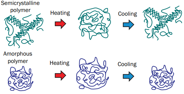
In addition to the economic factor, the proper choice of polymer is essential to ensure the quality and performance of the final part since the mechanical, thermal and processing properties directly influence the efficiency of the process and the characteristics of the injected part. Thermoplastics are divided into two main classes: amorphous and semicrystalline polymers. Both classes have particularities, mainly regarding the behaviour of molecular reorganization during the cooling phase, as can be seen in . These aspects directly affect the degree of crystallinity of the polymers, thus directly influencing the dimensional quality of the produced part. Additionally, the rate at which the polymer in the molten state cools also directly affects the formation of crystalline regions. Slow cooling allows more time for polymer chains to organize into crystalline structures, which may result in a higher degree of crystallinity. The presence of additives or fillers in the polymer matrix can also affect nucleation, facilitating the formation of crystalline regions. The degree of crystallinity can vary with the processing conditions and with the thermal history of the polymer: it is not a fixed property; thus, all these factors must be evaluated to define the adequate injection process.
. Microstructure of semicrystalline and amorphous polymers during processing. Adapted from Shoemaker [
1].
In the context of physical phenomena related to thermoplastic material during the injection process, it is important to note that volumetric contraction is an inherent property of polymer crystallization. If an excessive and non-uniform contraction occurs, either in general scope or in specific cross-sections of the part, this can result in unwanted deformations in the manufactured plastic part [
1]. Kazmer [
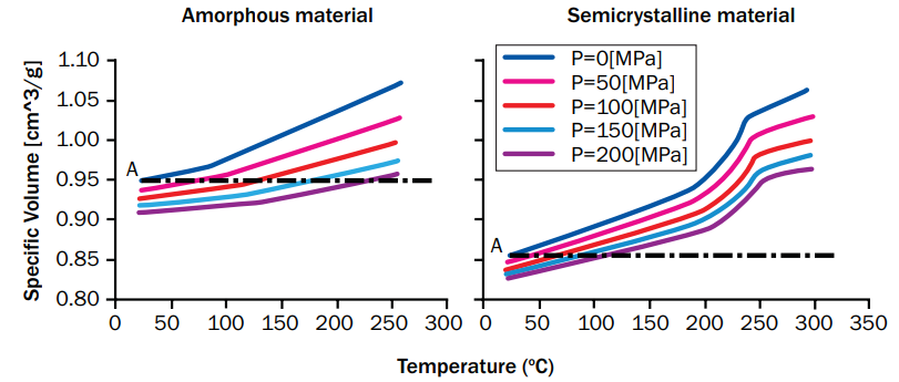
2] points out that semicrystalline polymers have high contraction rates during cooling when compared to amorphous materials. For this reason, the shrinkage rate of semicrystalline polymers is highly dependent on the cooling fluid temperature and cooling rate. In , Shoemaker [
1] presents the behaviour of the specific volume of amorphous and semicrystalline materials as a function of pressure and temperature.
. PVT diagrams for polymers. Adapted from Shoemaker [
1].
When analyzing the graphs in , it is possible to observe that semicrystalline polymers exhibit a “step-like” specific volume variation on cooling, mainly at the melting temperature. Semicrystalline polymers show an increase in specific volume with increasing temperature (at constant pressure) due to thermal expansion. They also show a decrease in specific volume with increasing pressure (at constant temperature) due to compressibility effects. In this perspective, Malloy [
3] mentions that, as the semicrystalline polymer presents amorphous and crystalline regions, during the cooling process, the “molten amorphous portion” cools and solidifies as it reaches its crystallization temperature. The significant decrease in volume associated with the phase change occurs as the polymer molecules pack into ordered crystalline regions, as seen in .
In addition to the choice of polymer, the mould material must also be taken into consideration, since the thermal properties will directly affect productivity (cycle time) and quality of the injected part. Historically, the thermoplastic injection process aimed at high production uses moulds made of steel based on its excellent mechanical properties (such as its high mechanical strength) and the extensive technical and scientific experience available regarding its use. Despite its several advantages, steel has a relatively low thermal conductivity compared to other materials, such as aluminium alloys, which display up to five times greater conductivity. The high thermal conductivity provides moulds made of aluminium with better heat distribution and dissipation, when compared to those observed when using steel moulds, reducing production cycle times by 20 to 80% [
4,
5,
6,
7,
8]. Nonetheless, as noted by Arieta Filho [
9], although aluminium exhibits superior thermal properties, it is more susceptible to mechanical wear than steel because of its lower mechanical strength.
Numerous studies have investigated the use of aluminium alloys in mould injection, particularly in prototyping. The thermomechanical properties of these alloys emphasize that aluminium is an excellent option for manufacturing prototype moulds [
10,
11,
12,
13,
14,
15]. In terms of mass production, aluminium alloys are more widely accepted in processes such as reaction injection moulding (RIM) [
16] and resin transfer moulding (RTM) [
17], as these require less mechanical effort than conventional injection moulding. However, Arieta et al. [
18] highlighted that leading automakers like GM, Nissan, and Tesla had adopted aluminium moulds for high-volume production.
In this context, Pereira et al. [
19] carried out a study regarding the use of steel and aluminium moulds and verified the presence of hot spots in the steel mould, which was a decisive factor in increasing the cooling time of the part by 22.86 s in addition to the time required for demoulding the part. This did not happen with the aluminium moulds, leading to a shorter cooling time. Thus, considering the time of 3 s for opening and 2 s for closing the mould, the total injection cycle time for the steel mould was 43.75 s, and for the aluminium mould was 23 s, which corresponds to a 47.43% reduction in the total cycle time. Marconi et al. [
5] explored the relationship between the material used for mould production (steel or aluminium) and the thickness of the injected part, examining how these factors impact the efficiency of the process in terms of the quantity and quality of the produced parts. The findings suggest that substituting steel moulds with aluminium alloys can significantly shorten the injection moulding cycle, with reductions ranging from 57.1% to 72.5%.
Despite the extensive research on the application of aluminium moulds, there is limited literature on how the thermal properties of this material impact injection moulding, resulting in uncertainties regarding the optimal injection parameter ranges. Additionally, there are no specific references concerning its use in the production of parts from different classes of polymers, necessitating an investigation into the feasibility of this alloy for manufacturing both amorphous and semicrystalline components. Insights into how these materials behave under different processing conditions could potentially promote the use of aluminium tooling in specialized high-volume injection moulding applications.
In view of the above, the present study aims to evaluate the differences found in the injection parameters of a plastic part, simulated in steel and aluminium moulds, using amorphous and semicrystalline polymers. Thus, this work is divided into three sections: the first one consists of an approach to the methodology regarding the conduction of the rheological simulations, as well as the presentation of the mould’s materials and the polymers; the second one presents the results of simulations and statistical analyses; and the third one presents the conclusions of this work.
2. Materials and Methods
The Taguchi experimental planning is a fractioned factorial experimental planning method, which consists of executing only a fraction of the total number of combinations of the input variables. Moita [
20] states that Taguchi himself classified this method as an “offline quality control”, because its application involves a small number of samples from trial phases, which present high variance levels in terms of quality parameters in comparison with production parts (“online quality control”). Rosa et al. [
21] point out that the Taguchi method allows for the determination of the optimum combination of factors and interactions that influence the variable-response behaviour from a given process, requiring fewer samples and decreasing testing costs without affecting the conclusions.
Given that a Design of Experiments (DOE) performs the experiments in many cases, it is necessary to make use of statistical tools for a better understanding and interpretation of the results. For that purpose, the ANOVA is suitable since it allows for the identification of the most important parameters for a certain response variable. In this context, Montgomery e Runger [
22] highlight that the ANOVA is a statistical method that assists data interpretation and decision making, and to statistically test results in different conditions. The statistical variables used to assess the results are the R2, the P-Value and the intrinsic error of the model.
In this work, statistical methods are applied to the numerical simulations’ results for the identification of the processing parameters of different polymers (amorphous and semicrystalline) to assess the performance of different mould materials (steel and aluminium). This work aims to evaluate the feasibility of mould injecting such polymers in those mould’s materials, in terms of production time and quality of the moulded part. The numerical simulations were performed with the software MoldFlow 2024
TM, while the statistical tests were carried out with the statistics software Minitab 19
TM.
2.1. Polymers and Mould Materials
The amorphous polymers considered in this work were the Acrylonitrile Butadiene Styrene (ABS) and the Polycarbonate (PC). Regarding the semicrystalline polymers, this work considered Polypropylene (PP) and Polyamide (PA). These thermoplastics are widely used in injection moulding processes. Furthermore, it is worth highlighting that the materials’ selection considered the differences related to their mechanical and physical properties, e.g., the elastic modulus, the Poisson’s ratio, and the density. The processing ranges of the materials were also considered, particularly the molten and mould temperature. All the polymers selected comply with the golden quality indicators, which means that their injection moulding data were obtained in laboratory environments and approved by Autodesk, the company that owns MoldFlow
TM. The information about the polymers is shown in
. The processing parameters are shown in
.
.
Polymers properties obtained through MoldFlowTM.
| Polymer |
Manufacturer |
Commercial Name |
Elastic Modulus (MPa) |
Poisson’s Ratio |
Density (kg/m3) |
| Acrylonitrile butadiene styrene (ABS) |
Kingfa Sci & Tech Co., Ltd. Qingyuan (China) |
HR-527A |
2308–2326 |
0.37–0.38 |
1045 |
| Polyamide (PA) |
Kuraray
Tokyo (Japan)
|
Genestar R480G |
3737–4228 |
0.36–0.37 |
1561 |
| Polycarbonate (PC) |
Covestro
Leverkusen (Germany)
|
Makrolon 2807 |
2283–2307 |
0.39 |
1202 |
| Polypropylene (PP) |
Kingfa Sci & Tech Co., Ltd.
Qingyuan (China)
|
ABP-2036 GT |
1908–2139 |
0.314 |
1045 |
The recommended operating range for mould and melt temperature for each polymer according to the Moldflow
TM library is shown in
.
.
Recommended operating range obtained through MoldFlowTM.
| Polymer |
Mould Temperature (°C) |
Melt Temperature (°C) |
| ABS |
40–80 |
210–260 |
| PA |
140–160 |
330–350 |
| PC |
80–120 |
280–320 |
| PP |
20–50 |
190–245 |
To perform the numerical simulations, AISI P20 steel was used for the steel mould, due to its wide use in the injection process. Regarding the aluminium alloy, the 7075-T651 alloy was used due to its high mechanical strength, which allows it to be used in high-production processes.
shows the mechanical and thermal properties of the mould materials used.
.
Mechanical and thermal properties of mould materials.
| Properties |
AISI P20 |
Aluminium 7075-T651 |
| Density (kg/m3) |
7800 |
2795.6 |
| Thermal Conductivity (W·m−1·K−1) |
29 |
137 |
| Coefficient of thermal elasticity (K−1) |
1.2 × 10⁻⁵ |
2.35 × 10⁻⁵ |
| Elastic modulus (GPa) |
205 |
70 |
| Heat capacity (J·kg−1·K−1) |
460 |
931.5 |
| Poisson’s ratio |
0.29 |
0.34 |
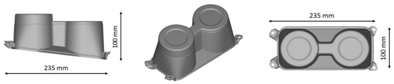
The geometry chosen as a case study for the development of the present work was an automotive cup holder with a nominal thickness of 2 mm, which includes geometric complexity and high productivity, as can be seen in
.
. CAD views of injection moulded par (cup holder).
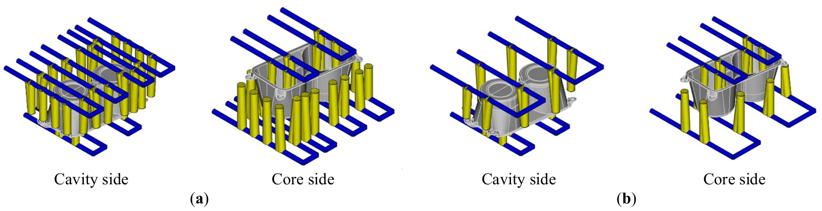
Based on the recommendations proposed by Kazmer [
2] and considering that the thermal conductivity of aluminium is higher steel’s, the cooling systems of these moulds have geometrical differences in relation to the distances between the channels and in relation to the surface of the mould cavity. Thus, the designed cooling systems considered the use of 26 and 14 baffles for the steel and aluminium moulds, respectively. For the baffle diameter values, 16 mm was adopted on the fixed mould plate (cavity) and 14 mm for those positioned on the movable plate (core).
shows the differences found in the configuration of the cooling systems for the steel and aluminium mould.
. Mould cooling system: (<b>a</b>) steel and (<b>b</b>) aluminium.
Initially, experimental plans were carried out only considering isothermal analysis to define the ideal processing conditions for the filling and compacting phases to maximize the dimensional quality of the part. These simulations consider as a boundary condition that the surface of the mould is maintained at a constant temperature, which allows idealizing the cooling system for the condition of the best possible temperature distribution. Thus, four experimental plans were carried out containing a total of 74 combinations (for each polymer) referring to the FPW module of MoldFlow
TM, totalling 296 rheological simulations related to this module. Each planning included six injection parameters: mould temperature, melt temperature, injection time, percentage of filled volume for switching control, packing time and packing pressure (as a function of the maximum injection pressure). The factors were divided into different levels, with 3 levels for mould temperature, melt temperature and percentage of filled volume for switching control; and 4 levels for injection time, packing time and packing pressure.
shows the levels used for each injection parameter in relation to the polymers used in the simulations.
.
Injection levels and parameters of the experimental planning (FPW).
| Polymer |
Melt Temperature (ºC) |
Mold Temperature (ºC) |
Injection Time (s) |
By % Volume Filled |
Packing Time (s) |
Packing Pressure (%) |
| ABS |
210–235–260 |
40–60–80 |
1–2–3–4 |
97–98–100 |
2–4–7–10 |
60–70–80–90 |
| PA |
330–340–350 |
140–150–160 |
1–2–3–4 |
97–98–100 |
2–4–7–10 |
60–70–80–90 |
| PC |
280–300–320 |
80–100–120 |
1–2–3–4 |
97–98–100 |
2–4–7–10 |
60–70–80–90 |
| PP |
190–217–245 |
20–35–50 |
1–2–3–4 |
97–98–100 |
2–4–7–10 |
60–70–80–90 |
In order to determine which parameters in
have the greatest influence on warpage results, four analyses of variance (ANOVA) were conducted using data from FPW simulations for each type of polymer. The purpose is to evaluate whether the use of different polymers significantly affects the results of the statistical test.
Based on the process parameters obtained in the previous analysis, the methodology proposed by Soares et al. [
23] was used for the optimization of process parameters related to the cooling step. These authors suggest combining the geometric configuration of the cooling system, established on literature recommendations, with the other parameters defined in the cooling analysis step, so that certain quality factors are achieved. These factors are related to the temperature uniformity of the mould cavity and cooling system efficiency. Thus, if the proposed cooling system (
) meets the recommendations in the literature, the next step consists of carrying out new experimental planning, contemplating combinations that allow the variation of temperature, pressure or flow of the cooling fluid. The objective of this second stage is to reach the optimal values related to mould cooling, so that it can achieve the best possible heat distribution (uniformity) associated with the shortest cooling time, maximizing process productivity and part quality.
From the procedure reported above, four experimental plans were carried out (one for each polymer), totalizing 16 combinations. Each planning considers two factors: temperature and pressure of the coolant, which were divided into 4 different levels, varying the intervals from the values obtained in the injection parameters. To determine the temperature range of the coolant, the mould temperature determined in the isothermal analysis is the main parameter. Regarding the pressure, the values varied from the turbulence conditions acceptable to the process (turbulent regime) and operating conditions of the injection machine. In addition, as they are materials from different moulds, the same experimental planning was chosen for a better comparison of the results found in the cooling step.
3. Results
To better present the results found in this work, this section was divided into three subsections. The first one presents the configuration of the parameters that minimized the warpage, considering the isothermal analyses, as well as the ANOVA in relation to each polymer. The second shows the results related to the cooling step, regarding the cooling time and the convergence of each polymer in relation to the permanent regime of the injection process. Finally, the third one presents the results related to the warpage of the part.
3.1. Filling and Packing Results
The configurations that minimized the warpage of the part were obtained through the DOE created from the six injection parameters (
). Considering the nature of the polymers (amorphous and semicrystalline), as well as their properties, each material presented an ideal configuration, as can be seen in
.
.
Optimal configuration of the Filling and Packing parameters of the MoldFlowTM module.
| Polymer |
Melt Temperature (ºC) |
Mould Temperature (ºC) |
Injection Time (s) |
By % Volume Filled |
Packing Time (s) |
Packing Pressure (%) |
Packing Pressure (MPa) |
| ABS |
210 |
40 |
4 |
97 |
2 |
90 |
137.3 |
| PA |
350 |
150 |
1 |
97 |
2 |
90 |
4.7 |
| PC |
280 |
100 |
1 |
97 |
7 |
90 |
92.3 |
| PP |
245 |
50 |
4 |
100 |
10 |
80 |
16.3 |
From the analysis of the results presented in
, it was possible to observe a difference in the FPW parameters for the polymers used. Regarding the injection parameters, the values referring to the packing pressure stand out: the amorphous polymers presented higher pressures compared to semicrystalline polymers. According to Rosato et al. [
24] (2000), amorphous polymers gradually soften as they are heated, but do not flow as easily during moulding as semicrystalline materials, requiring higher injection pressures. It is important to highlight that high pressures may be an impediment to the use of moulds made of aluminium, since these materials have lower mechanical strength when compared to steel [
25,
26,
27].
An ANOVA was performed based on a first-order polynomial regression model for each polymer with the warpage results from the MoldFlow
TM FPW module simulations (as shown in
). The intention was to verify which of the parameters used had the most influence on the results. The criterion adopted to verify the quality of the fit of the models to the data was the R2 value (regression) and
p-value for the parameters. The developed models follow the character described in
Equation (1)
where $$w ,$$ $$m_{e} t , m_{o} t , i t , v f , p t , p p$$ represent, respectively, the variables warpage, melt temperature, mould temperature, injection time, by % volume filled, packing time, packing pressure; and k represents the value of the constant that best fitted the model.
shows the results related to ANOVA for each model developed for each polymer, as well as the contribution of each parameter regarding the prediction of part warpage.
.
ANOVA data for the warpage prediction models for each polymer obtained through MinitabTM.
| Model Parameters |
Semicrystalline Polymers |
Amorphous Polymers |
| PP |
PA |
ABS |
PC |
| Source |
Contribution |
p-value |
Contribution |
p-value |
Contribution |
p-value |
Contribution |
p-value |
| Regression |
79.44% |
0.00000 |
87.31% |
0.000 |
93.69% |
0.000 |
89.63% |
0.00000 |
| $$m_{e} t$$ |
56.25% |
0.00000 |
34.90% |
0.000 |
57.42% |
0.000 |
43.14% |
0.00000 |
| $$m_{o} t$$ |
0.07% |
0.04735 |
0.87% |
0.064 |
5.13% |
0.000 |
16.92% |
0.00000 |
| $$i t$$ |
6.36% |
0.00000 |
45.88% |
0.000 |
13.52% |
0.000 |
6.02% |
0.00000 |
| $$v f$$ |
8.62% |
0.00000 |
1.51% |
0.000 |
2.15% |
0.000 |
0.72% |
0.00000 |
| $$p t$$ |
2.03% |
0.00004 |
1.45% |
0.007 |
3.84% |
0.000 |
8.33% |
0.00000 |
| $$p p$$ |
6.11% |
0.00000 |
2.69% |
0.000 |
11.63% |
0.000 |
14.51% |
0.00000 |
| Error |
20.56% |
|
12.69% |
|
6.31% |
|
10.37% |
|
| Lack-of-Fit |
20.56% |
|
12.69% |
|
6.31% |
|
10.37% |
|
| Pure Error |
0.00% |
|
0.00% |
|
0.00% |
|
0.00% |
|
| Total |
100.00% |
|
100.00% |
|
100.00% |
|
100.00% |
|
Based on the results from
, it was possible to observe that the melt temperature is the most significant parameter regarding the warpage, except for the PA, for which the injection time showed a greater contribution. This influence is related to the high thermal conductivity of polyamide, which allowed the extraction times to be 3–4 times shorter compared to the other polymers evaluated. Thus, as the time interval is reduced for the crystallization process of the material to occur, the injection time ends up having a greater influence on warpage. It is worth mentioning that the evaluations regarding the FPW simulations do not depend on the type of the mould material, since the temperature of the mould cavity is kept constant during the whole process.
3.2. Cooling Results
Four experimental plans were carried out, varying the cooling fluid processing parameters and based on the injection parameters obtained in the isothermal analyses (
). The temperature and pressure of the cooling fluid were varied in four levels, generating a plan with 16 combinations. It is worth mentioning that water was used as a cooling fluid for the PP, PC and ABS polymers, differing from the PA polymer, for which oil was used. The difference in the cooling fluid was due to the high mould temperature (150 °C) obtained in the isothermal analyses. In addition, a different pressure variation was used for oil compared to water due to the higher viscosity presented by the former, thus ensuring turbulence in the process.
shows the data for the experimental designs of the cooling of each polymer.
.
Taguchi experimental planning of cooling obtained through MinitabTM.
| Polymer |
Coolant |
Coolant Temperature (ºC) |
Coolant Pressure (bar) |
| ABS |
Water |
20–25–30–35 |
0.5–1.0–1.5–2.0 |
| PA |
Oil |
130–135–140–145 |
2.0–4.0–6.0–8.0 |
| PC |
Water |
80–85–90–95 |
0.5–1.0–1.5–2.0 |
| PP |
Water |
30–35–40–45 |
0.5–1.0–1.5–2.0 |
Evaluating the quality criteria related to the cooling system proposed by Soares et al. [
23], the processing parameters approved in the methodology for each material are presented in
. The results obtained that met the quality criteria used the hot cooling fluid (above room temperature). According to Jeng et al. [
28], with a high mould surface temperature, the surface quality of the part will be better, although the cooling time and, consequently, the cycle time will increase.
.
Approved cooling processing conditions.
| Polymer |
Approved Cooling Processing Conditions |
| Coolant Temperature (ºC) |
Coolant Pressure (bar) |
| Steel |
Aluminium |
Steel |
Aluminium |
| ABS |
30–35 |
0.5–1.0–1.5–2.0 |
| PA |
140–145 |
2.0–4.0–6.0–8.0 |
| PC |
90–95 |
0.5–1.0–1.5–2.0 |
| PP |
40–45 |
0.5–1.0–1.5–2.0 |
shows the results obtained from the approved processing conditions. For each polymer, cooling intervals were determined for the steel and aluminium mould, based on the quality criteria defined by Soares et al. [
23]. The table displays two important results: one for the cooling time intervals and another for the total cycle time for each mould material. It is important to highlight that there were hotspots in the steel mould cavity for all polymers, requiring an increase in cooling time to meet the quality criteria. Regarding the aluminium mould, only the mould that operated with polyamide (PA) presented hotspots, which also required additional time to uniform the cavity surface.
.
Results of the approved processing conditions.
| Polymer |
Cooling Time (s) |
Cycle Time (s) |
| Steel |
Aluminium |
Steel |
Aluminium |
| ABS |
13–20 |
6–7 |
24–31 |
17–18 |
| PA |
42–44 |
11–14 |
50–52 |
19–22 |
| PC |
13–19 |
6–7 |
26–32 |
19–20 |
| PP |
13–21 |
0 |
32–40 |
19 |
Although amorphous polymers require longer periods to reach the extraction temperature than semicrystalline polymers, due to their disordered molecular structure, they showed lower cycle times when using steel moulds. This is because the injection parameters obtained in the FPW analyses concerning the times (injection and packing) were smaller. For moulds made of aluminium, semicrystalline polymers showed more significant reductions in cycle time compared to amorphous materials. Polypropylene showed a cycle time reduction between 40.6 and 52.5% compared to steel moulds, while polyamide showed a reduction between 56 and 63.5%. According to Rosato et al. [
24], the high degree of molecular order of semicrystalline polymers tends to make their thermal conductivity values twice as high as those of amorphous plastics. Furthermore, the high heat dissipation and uniformity in the aluminium mould are high, the polypropylene did not require additional cooling time to achieve the quality factors. Although polyamide obtained the lowest values for extraction time among all the polymers evaluated, the cooling time required to achieve the quality criteria of uniformity in the cavity was the highest. This is due to the high temperature of the mould and the use of oil as a cooling fluid, which has inferior heat transfer properties compared to water.
Unlike the cycle time results presented in
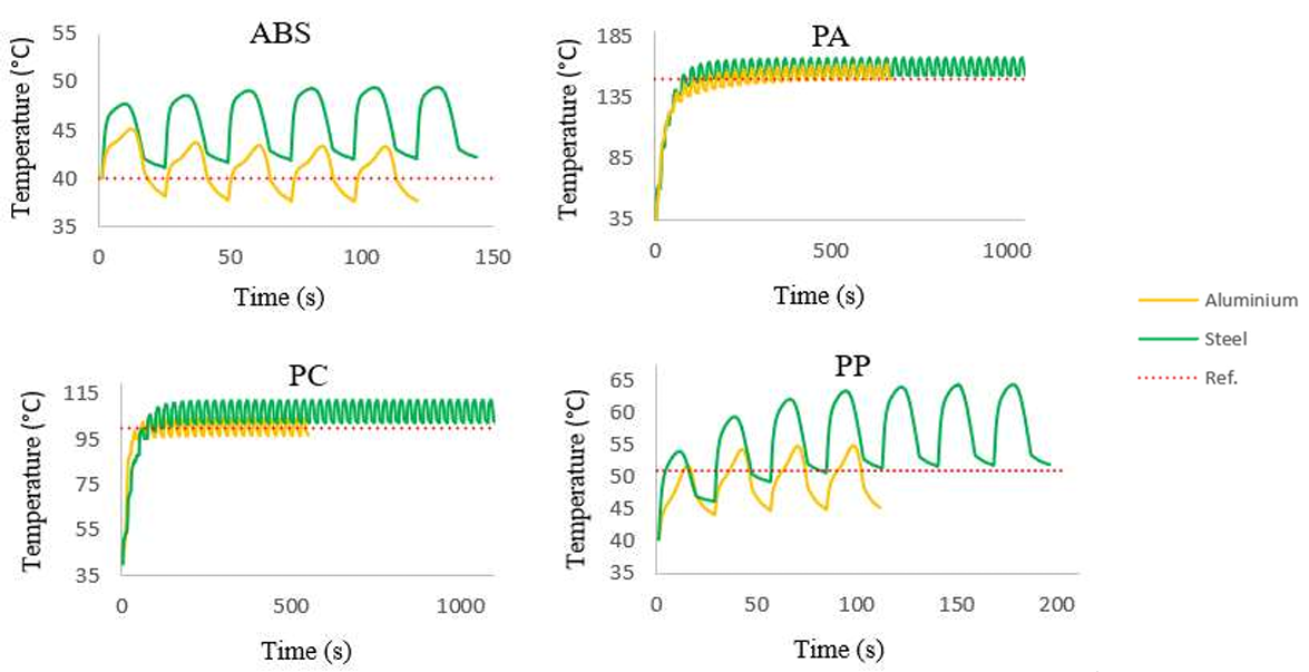
, the time for convergence in relation to the permanent regime showed discrepancies both in relation to the mould materials and in relation to the polymers. To carry out the evaluation, the stopping criteria used for the transient cooling simulations were defined from the following values: when achieving a total of 100 operating cycles or a maximum mould temperature variation of 0.5 °C between cycles.
shows the graphs showing the behaviour of the processes from the start of injection.
. Transient profile of the injection process until reaching the permanent regime obtained through MoldFlow<sup>TM</sup>.
From the results in
, it is possible to see that the aluminium mould tends to converge to the steady state faster when compared to the steel mould. This behaviour occurs because the first has a significantly higher thermal conductivity than the former, so the heat is transferred faster through the aluminium during mould cooling, leading to faster convergence to the steady state. According to Rosato et al. [
24], simulation software that uses transient analysis to assess the steady state of the mould and the part also takes into account the variation in the specific heat and thermal conductivity of the polymer during cooling, which justifies the discrepancy in relation to the time to reach the permanent regime of each material. Overall, the number of cycles required to reach the steady state behaviour was linked to the temperatures of the moulds. Thus, moulds that use higher temperatures need more time to reach a steady state.
The same processing conditions for each evaluated polymer (temperature and pressure of the cooling fluid) were used to evaluate the results in all four cases. In addition, to evaluate the behaviour of the graphs, the same node as the mould surface was used, ensuring sensitivity to the behaviour of the data.
3.3. Warpage Results
The results in
show the outcomes obtained through the experimental planning using the FPW modules (isothermal simulations) exclusively, considering the approved combinations listed in
.
.
Warpage results from FPW analyses (isothermal).
| Polymer |
FPW Warpage (mm) |
| ABS |
0.401 |
| PA |
3.506 |
| PC |
0.566 |
| PP |
0.676 |
The maximum warpage ranges were determined for each polymer type and mould material after performing the full cycle analysis of the approved processing conditions in the cooling step (as shown in
).
shows the warpage results, considering the transient analysis.
.
Warpage results of the complete cycle.
| Polymer |
Maximum Warpage (mm) |
Variations from the Warpage of the Isothermal and Transient Simulations (Ref.) (%) |
| Steel |
Aluminium |
Steel |
Aluminium |
| ABS |
0.52–0.57 |
0.44–0.51 |
29.7–42.1 |
9.7–27.2 |
| PA |
3.48–3.50 |
3.49–3.50 |
0.2 *–0.7 * |
0.2 *–0.5 * |
| PC |
0.65–0.69 |
0.55–0.58 |
14.8–21.9 |
2.5–2.8 * |
| PP |
0.72–0.80 |
0.68–0.73 |
6.5–18.3 |
0.6–8.0 |
The results in
show the maximum warpage for steel and aluminium moulds for each material. In general, the aluminium mould presented smaller warpages than the steel mould, and therefore presented smaller variations in relation to the isothermal simulations. These results are justified by the fact that the high conductivity of aluminium allows rapid heat dissipation and consequently, greater cavity uniformity, reducing deformations inherent to differential cooling.
The amorphous materials showed the lowest values for both moulds, and the greatest variations in isothermal simulations compared to semicrystalline materials, which indicates that the cooling system had a greater influence on the dimensional quality of these materials. This discrepancy is due to molecular reorganization during the cooling phase. However, the warpage of these materials is small; for the most acute case, the variation corresponds to 42.1%, which is equivalent to 0.12 mm. Thus, despite having greater variations, they do not compromise the dimensional quality of the part. In general, the reduced variations in isothermal simulations indicate that the warpage is more related to the injection processes than the cooling parameters.
4. Conclusions
To optimize the processing parameters for different classes of polymers, this study was developed based on the evaluation of the main injection and cooling parameters, aiming at the productivity and dimensional quality of parts produced in steel and aluminium moulds. When evaluating the results in general, aluminium moulds show a significant reduction in relation to the total cycle time, one that ranges from 25 to 63.5% for all polymers.
It is important to mention that, in relation to the mould materials, the aluminium mould exhibited the lowest warping results and smaller variations compared to the isothermal analyses for all polymers. This outcome indicates that its thermal properties enable efficient dissipation and uniformity of the mould surface, leading to better control during polymer cooling and reducing warping caused by differential cooling.
For amorphous polymers, the results indicated that higher pressures were required to fill the cavity completely. Therefore, due to their lower rigidity and high thermal conductivity, aluminium moulds are not recommended for this type of polymer in high-volume production processes. Conversely, semicrystalline polymers required lower pressures, and aluminium moulds provided better dimensional quality than steel moulds. This result suggests that these tools could be a viable alternative for manufacturing large volumes of parts using aluminium moulds.
In this scenario, the use of numerical simulations associated with experimental planning to verify the processing parameters of different polymers proved to be a very useful tool, as it allows the evaluation of nuances, both in relation to the quality of the part and in relation to the structural integrity of the moulds. These nuances associated with project requirements, such as mechanical properties, dimensional quality, among others, provide fundamental information to designers during the evaluation of the use of amorphous and semicrystalline materials in steel and aluminium moulds.
Acknowledgments
This work is a partial result of the DEMALAP Project—Aluminium Mould Demonstrator for High Production sponsored by the Rota 2030 Program of the Federal Government described in Law No. 13,755/2018 and is coordinated by FUNDEP. The executors of the project are the universities SENAI CIMATEC, UFBA and UFSC. We are grateful to the other project partners for their support: ESSS Engineering Simulation and Scientific Software Ltd.a, Ford Motor Company Brasil Ltd.a; Moldit Brasil Ltd.a, Open Mind Tecnologia Brasil Ltd.a, Renault do Brasil S.A, SMRC Fabricação e Comércio de Produtos Automotivos do Brasil Ltd.a and Union Indústria de Moldes e Comércio Atacadista de Máquinas Eireli.
Author Contributions
Conceptualization, P.G.C.S.M., E.M.S.A. and A.S.R.J.; Methodology, P.G.C.S.M. and A.S.R.J.; Software, P.G.C.S.M.; Investigation, P.G.C.S.M. and E.M.S.A.; Writing—Original Draft Preparation, P.G.C.S.M. and E.M.S.A.; Writing—Review & Editing, R.L.L.F., C.V.F., V.E.B. and A.S.R.J.; Supervision, A.S.R.J.
Ethics Statement
Not Applicable.
Informed Consent Statement
Not Applicable.
Data Availability Statement
The data supporting the conclusions of this study are available from the corresponding author upon reasonable request.
Funding
This work is involved in a project sponsored by the Brazilian Federal Government’s Rota 2030 Program described in Law No. 13.755/2018 and is coordinated by FUNDEP.
Declaration of Competing Interest
The authors declare that they have no known competing financial interests or personal relationships that could have appeared to influence the work reported in this paper.
References
1.
Shoemaker J. Moldflow Desing Guide: A Resource for Plastic Engineers; Hanser Gardner Publications: Framingham, USA, 2006.
2.
Kazmer DO. Injection Mold Design Engineering, 2nd ed.; Hanser: Munich, Germany, 2016.
3.
Malloy RA. Plastic Part Design for Injection Molding: An Introduction, 2nd ed.; Carl Hanser Verlag GmbH Co KG: Munich, Germany, 2010.
4.
Lammon B. Let’s Be Clear about Aluminium, MouldMaking Technology. 2013. Available online: https://www.moldmakingtechnology.com/articles/lets-be-clear-about-aluminum (accessed on 16 April 2023).
5.
Marconi P, Amarante E, Ferreira C, Beal V, Ribeiro Junior A. Steel and Aluminum Molds: The Effect of Thickness on Productivity and Part Quality.
SAE Int. J. Mater. Manf. 2024,
17, 341–353. doi:10.4271/05-17-04-0024.
[Google Scholar]
6.
Bryce DM. Plastic Injection Molding: Mold Design and Construction Fundamentals; Society of Manufacturing Engineers: Dearborn, MI, USA, 1998.
7.
Malnati P. High-Performance Alloy Increases Performance Capability of Aluminum Molds. MoldMaking Technology. 2020. Available online: https://www.moldmakingtechnology.com/articles/high-performance-alloy-increases-performance-capability-of-aluminum-molds (accessed on 15 August 2024).
8.
Shrader DR. Comparing 3D-Printed Conformal-Cooled Steel Molds to Aluminum Molds. MouldMaking Technology. 2020. Available online: https://www.moldmakingtechnology.com/articles/comparing-3d-printed-conformal-cooled-steel-molds-to-aluminum-molds (accessed on 16 August 2024).
9.
Arieta Filho FG. Ligas de alumínio de alta resistência para moldes de injeção de termoplásticos: ficção ou realidade? Revista Ferramental, Brazilian Magazine of the Tooling Industry, 8th ed. 2006. Available online: https://issuu.com/revistaferramental8/docs/edi____o_8 (accessed on 18 August 2024).
10.
Greškovič F, Dulebová L, Duleba B, Krzyżak A. Criteria of maintenance for assessing the suitability of aluminum alloys for the production of interchangeable parts injection mold.
Eksploatacja i Niezawodność 2013,
15, 434–440.
[Google Scholar]
11.
Huzaim NHM, Rahim SZA, Musa L, Abdellah AEH, Abdullah MMAB, Rennie A, et al. Potential of rapid tooling in rapid heat cycle molding: A review.
Materials 2022,
15, 3725.
[Google Scholar]
12.
Zhong ZW, Leong MH, Liu XD. The wear rates and performance of three mold insert materials.
Mater. Des. 2011,
32, 643–648.
[Google Scholar]
13.
Gibson I, Rosen D, Stucker B. Additive Manufacturing Technologies 3D Printing, Rapid Prototyping, and Direct Digital Manufacturing, 2nd ed.; Springer: New York, NY, USA; Heidelberg, Germany; Dordrecht, The Netherlands; London, UK, 2015. doi:10.1007/978-1-4939-2113-3.
14.
Shaharuddin SIS, Salit M, Zainudin ES. A Review of the Effect of Moulding Parameters on the Performance of Polymeric Composite Injection Moulding.
Turk. J. Eng. Environ. Sci. 2006,
30, 23–34.
[Google Scholar]
15.
Krizsma S, Suplicz A. Monitoring and modelling the deformation of an aluminium prototype mould insert under different injection moulding and clamping conditions.
Results Eng. 2023,
20, 101556.
[Google Scholar]
16.
Bayer Corporation. “RIM Part and Mould Design”. Bayer Material Science. 2008. Available online: https://reactioninjectionmolding.com/wp-content/uploads/2013/09/RIM-PartMoldDesignGuide.pdf (accessed on 20 August 2024).
17.
Mazumdar S. Composites Manufacturing: Materials, Product, and Process Engineering, 1st ed.; CRC Press: Boca Raton, FL, USA, 2001.
18.
Arieta F, Francisco G, Marino MP, Dihlman C, Gonçalves M. Aplicação de Ligas de Alumínio em Moldes para Injeção de Termoplásticos. Revista Ferramental. 2019. Available online: https://www.revistaferramental.com.br/artigo/aplicacao-ligas-alumunio-moldes-para-injecaotermoplasticos/ (accessed on 21 August 2024).
19.
Pereira JAP, Jesus SGdA, Amarante EMdS, Júnior ASR, Ferreira CV, Beal VE. Moldes de injeção de alumínio: efeitos das propriedades térmicas do material do molde nos parâmetros de injeção e projeto do molde. In Proceedings of the 12th Brazilian Congress of Manufacturing Engineering, Brasília, Brazil, 10–12 May 2023.
20.
Moita CVNF. Implementação do método Taguchi e análise de experiências na fase de testes de moldes para injeção de plásticos. Master’s thesis, Mechanical Engineering, Technical University of Lisbon, Lisbon, Portugal, 2007.
21.
Rosa JL, Robin A, Silva MB, Baldan CA, Peres MP. Electrodeposition of copper on titanium wires: Taguchi experimental design approach.
J. Mater. Process. Technol. 2009,
209, 1181–1188. doi:10.1016/j.jmatprotec.2008.03.021.
[Google Scholar]
22.
Montgomery DC, Runger GC. Estatística Aplicada e Probabilidade Para Engenheiros, 4th ed.; LTC: Rio de Janeiro, Brazil, 2009; 514p.
23.
Soares AH, Marconi PD, Carvalho GG, Ribeiro Junior AS, Beal VE, Ferreira CV. Performance evaluation of cooling systems in injection moulds made of steel and aluminium through numerical simulations. In Proceedings of the 12th Brazilian Congress of Manufacturing Engineering, Brasília, Brazil, 10–12 May 2023.
24.
Rosato DV, Rosato DV, Rosato MG. Injection Molding Handbook, 3rd ed.; Springer: New York, NY, USA, 2000.
25.
Carvalho GG, Bayma GV, Martins MA, Ferreira CV, Beal VE, Ribeiro Junior AS. Thermomechanical Evaluation of Thermoplastics Injection Cycle Effects in Aluminium Moulds Using the Finite Element Method. In Proceedings of the Brazilian Manufacturing Engineering Congress; Springer Nature: Cham, Switzerland, 2023. doi:10.26678/ABCM.COBEF2023.COF23-0136.
26.
Sánchez R, Martinez A, Mercado D, Carbonel A, Aisa J. Rapid heating injection moulding: An experimental surface temperature study.
Polym. Test. 2021,
93, 106928.
[Google Scholar]
27.
Himmer T, Nakagawa T, Anzai M. Lamination of metal sheets.
Comput. Ind. 1999,
39, 27–33.
[Google Scholar]
28.
Jeng MC, Chen SC, Minh PS, Chang JA, Chung CS. Rapid mold temperature control in injection molding by using steam heating.
Int. Commun. Heat Mass Transf. 2010,
37, 1295–1304. doi:10.1016/j.icheatmasstransfer.2010.07.012.
[Google Scholar]