1. Introduction
Population growth, technological innovation, access to clean energy, and environmental concerns are some of the factors that compelled governments and scholars across the globe to hunt for alternate ways to generate electricity to fulfill the world’s continual increase in energy demand. Furthermore, due to considerations such as geographical location, lack of accessibility, and transportation infrastructure restrictions, a considerable proportion of rural and remote areas in Sub-Saharan Africa lack access to a steady power supply [
1,
2,
3]. Some of the conventional tactics deployed by the utility to address these challenges have not yielded positive outcomes. However, with the recent advancement in technology, renewable energy sources (RESs) are one of the possible solutions to these issues. Renewable energy provides cleaner energy and is capable of supplying electricity to rural areas and communities [
4]. Integrating RESs into distribution networks offers utilities and electricity consumers different technical, conservational, and financial benefits [
5,
6,
7]. The direction of power flow on the grid has also changed from unidirectional to bidirectional due to the emerging technology of grid integration of RESs. Power distribution operators and consumers are impacted positively and negatively by the change in the flow of power [
8,
9]. The concept of renewable energy-based microgrids was developed by researchers and governments to maximize the benefits and alleviate grid integration limitations [
10,
11]. Microgrid enhances grid integration of renewable energies, reduces transmission and distribution losses, and offers a dependable electricity supply. According to [
4], a microgrid is a power network unit that uses small power-generating sources, such as RESs and other distributed generation sources, connected with energy storage devices to meet the load demand. Microgrids can be classified into AC microgrids, DC microgrids, and hybrid microgrids. AC microgrid can be integrated into an existing traditional utility network without a special control system. DC microgrid is a distribution network comprising DC loads, energy storage systems, and renewable energy sources which are mainly DC output voltage. A hybrid microgrid is a group of interconnected conventional and renewable energy resources that are connected to end users and regulated by systems to enhance effective energy storage and use. The hybrid AC-DC microgrid enables simultaneous connection of variable AC and DC sources and their corresponding loads while reducing the number of power conversions required in individual AC or DC microgrids. According to [
12], DC microgrids based on distributed generation allow DC electricity to be utilized directly in DC household appliances. Because these systems eliminate the need for the AC-DC conversion step and improve electricity consumption, they have become more and more popular in a variety of fields. Furthermore, according to [
12], the use of DC microgrids can be grouped into three different modes. Mode A is the DC microgrid powered by the commercial network. A standalone DC microgrid with energy storage as power supply to the load is considered model B, while a standalone DC microgrid with energy storage for energy support is considered model C. Some of the technical issues associated with low-voltage DC microgrids such as Instability issues at LVDC-MGs, harmonics, virtual resistors, over-voltage, under-voltages, low inertia, and bidirectional power flow are discussed in [
13]. Authors in [
14] provide an overview of the comparison of existing DC microgrid and AC microgrid systems. The purpose of the study is to assess the feasibility of the low-voltage direct current distribution system and its effects on the development of society. In addition, the study provides valuable information for renewable energy planners and provides insights or solutions to bridge the gap between the current energy grid and future DC microgrids. The general overview of microgrids and performance evaluation of the system when connected to the power grid and off-grid, considering various power issue scenarios, are presented in this paper and the paper focuses mainly on AC microgrid. The microgrid under investigation consists of wind farms, a small hydroelectric power plant, and energy storage systems. The use of solar farm is not considered in this paper; however, it will be considered in the next paper. Some of the simulated instances for performance evaluation include stand-alone mode, grid-connected mode, and transition from one mode of operation to another. In the standalone mode of operation, the utility grid is intentionally decoupled from the microgrid so that both networks supply power to the connected loads independently. In grid-connected mode, the microgrid is directly coupled with the utility grid, and the system’s performance was investigated. In the transition from one mode of operation to another, the system was suddenly changed from grid-connected to stand-alone mode and the system performance was observed. Fault occurrences, an increase in micro-source power generation, an increase in loading systems, and sudden disconnection of RESs from the microgrid are some of the simulated and evaluated scenarios in each case. The network under investigation is molded and simulated using MATLAB/Simulink. Fault conditions, increased power generation, increase in loading systems, and sudden disconnection of renewable energy sources from the microgrid are some of the simulated and evaluated scenarios in the paper. The results of the simulations demonstrated the performance of the microgrid system under various scenarios on the grid. Also, the simulation results show the effectiveness of the battery storage system in stabilizing and restoring the network stability during various disturbances on the grid. The paper is structured as follows: Section 2 provides a comprehensive overview of microgrids. Section 3 discusses the network under investigation and simulation scenarios, Section 4 presents simulation results and discussion, while microgrid limitation, conclusion, and future works are presented in sections 5 and 6 respectively.
2. Microgrids Overview
Scholars have assigned several meanings to microgrids. A microgrid is described by the US Department of Energy as a set of unified distributed generation sources (DGs) and loads within definite electrical restrictions that can operate as an independent controlled entity on the electrical grid [
5,
6,
7]. European Union research project defines microgrids as a low-voltage (LV) distribution network consisting of DGs, energy storage units, and variable loads that can operate when coupled or decoupled from the utility grid [
15,
16]. Furthermore, in [
17,
18] a microgrid (MG) is said to be a moderate power network with DGs, monitoring circuits, and 71 electrical loads. Generally, the given definitions recognized the significance of distributed energy sources in microgrids and their ability to function as an independent entity on the grid.
2.1. Components and Classification of Microgrids
Microgrid comprises electricity generation sources, energy storage systems, and electrical loads that are electrically interconnected [
16,
17,
19,
20]. shows the fundamental structure of a microgrid. Microgrids (MGs) generate electricity using renewable energy sources like solar, wind, small hydropower plants, and micro-turbines. Another essential component of MGs is energy storage units. Energy storage systems (ESSs) ensure an uninterrupted and continuous power supply to the loads and contribute to the stability of the microgrid due to the irregular supply from the RESs. Storage systems can enhance the power quality by maintaining the grid’s nominal voltage. BESSs are commonly used with microgrids [
17,
21]. Different loads, such as AC, DC, linear and non-linear, and dynamic loads, can be integrated into microgrids. Load management systems are vital components in microgrid systems. Microgrid energy loads have a wide range of controllable characteristics, from critical loads to adjustable loads. The use of critical loads, such as hospital loads, cannot be shaded; the use of adjustable loads, like heating or cooling, lighting, and pool filters, can temporarily be shaded for peak load reduction. Other loads, like business buildings with backup power sources and residential buildings, should be shaded during emergencies to maintain microgrid reliability and avoid power outages [
22,
23]. Power conditioning units (PCUs), energy management systems, and control systems are other essential elements of MG. In MG, energy conversion units comprise transformers (step up and step down) and PCUs that convert produced power to the necessary and suitable power and voltage to be provided directly to the grid or end user [
24]. Hybrid microgrids require an energy management system (EMS) due to the range of intermittent energy sources involved. The EMS must be able to control all interconnected power generation sources and provide swift responses to situations on the grid [
24,
25,
26].
. Basic structure of a microgrid.
Microgrid Classification Microgrids are classified based on architecture, supervisory control, modes of operation, and phases [
27,
28]. However, classification based on the microgrid architectures and voltage characteristics is reviewed in this paper [
29,
30,
31,
32,
33,
34].
• AC Microgrid
• DC Microgrid
• Hybrid Microgrid
2.2.1. AC Microgrid (ACMG)
This is the most implemented MG. In this category, various forms of renewable energy sources are integrated into the grid using a power electronic converter (PEC) [
35]. The AC microgrid offers minimal modifications for integration into the existing grid. It is commonly used in medium- and low-voltage distribution networks to enhance current flow and minimize power loss in transmission lines. In addition, the ability to integrate with traditional distribution networks or operate in stand-alone mode makes the system flexible, allowing it to operate directly with AC distribution devices such as AC loads. It does not require any inverters for AC loads, and the protection system is cost-effective. However, system integration causes stability and power quality issues for distribution operators [
32,
36,
37]. Lower conversion efficiency, high DC-AC conversion costs, controllability challenges due to frequency factors, voltage regulation, unbalanced compensation, and poor power supply reliability, which can impede device performance, are some of the challenges of an AC microgrid [
38,
39,
40,
41]. However, the use of advanced control technology solves these problems [
32,
36,
42].
2.2.2. DC Microgrid (DCMG)
Due to modern advancements in electrical power generation techniques, several power conversion units have been employed for various applications in power systems [
24]. Furthermore, DC-based RESs and various forms of ESS technologies provide new opportunities for the development of DC microgrids. Benefits of DC microgrids include limited energy conversion processes and reactive current restrictions [
32,
43,
44]. DC/AC PCU is required for connecting a DC microgrid to an existing traditional power distribution network. DC and AC microgrids are very similar in their operating modes. The main difference is that DC microgrids use DC buses for connectivity, while AC buses connect DGs and utility network loads together. The ideal operating voltage for a DC bus is between 350 and 400 Volts. The main DC bus can be separated into other low-voltage buses to meet the low-voltage prerequisites of electronic loads. In contrast, DC-type microgrid high-voltage DC-DC converters increase the connectivity of low-voltage sources like solar modules with a voltage range between 20 to 45 volts by supplying them with high voltage from the DC bus bar. DC-Microgrid offers several advantages to distribution operators over AC-Microgrid. Transmission efficiency due to non-reactive power, supply reliability even in remote locations, relatively small wiring due to high voltage at low temperatures, and convenient system control without causing complications such as synchronization, harmonics, reactive power, and frequency regulation are some of the advantages of DC microgrids [
45,
46]. However, some disadvantages include inconsistent AC load proportional to the number of AC loads and large voltage drop in the absence of a reactive power source, especially for large systems [
37,
47,
48,
49,
50,
51].
2.2.3. Hybrid Microgrids (HMGs)
HMGs are achieved by integrating ACMG and DCMG on the same distribution network. In HMG, AC, and DC elements are separately integrated into their respective sections, therefore grid harmonization is not required for the energy generation and storage components. Since AC and DC elements are separately integrated into their respective sections in HMG, grid harmonization is not required for the energy generation and storage segment [
52,
53,
54]. Combining the advantages of ACMG and DCMG, HMG enhances the network’s reliability and efficiency and enables easy integration of different RESs and ESSs into the existing distribution network [
27,
55,
56]. HMG reduces the number of energy conversion processes and thus reduces power loss [
57,
58]. However, the high cost of complex storage and control systems poses challenges for the microgrid. Furthermore, MGs may be grouped according to their usage into utility, institutional, commercial, industrial, and transport microgrids [
11,
59].
2.3. Microgrid Mode of Operations
Microgrids can operate in both stand-alone and grid-connected modes [
60,
61,
62].
2.3.1. Grid-Connected Modes
The microgrid is connected to the grid through a common point coupling (PCC). Depending on the amount of power generated and customers’ demand, excess power generated can be shared with the utility grid through PCC [
19,
63]. Distribution network feeders must be adequately equipped for this purpose.
2.3.2. Stand-alone Mode of Operation
This is a situation where MGs operate autonomously with connected loads when detached from the main utility power network. Microgrids can be intentionally or unintentionally disengaged from the utility network to operate independently. In this condition, MG supplies electricity to the connected loads through the micro-sources. The intentional disconnection of microgrids is predefined and follows a predefined process, while unintentional islanding can be a result of unwanted situations such as faults on the grid. During this time, the microgrid can automatically switch from grid-tied to stand-alone mode through a protective device. In autonomous operation, differences in the generated power and load demand cause voltage and frequency fluctuations in the network. In renewable energy-based MG, the output power of each micro-source must be effectively coordinated to enhance the stability of the system. Microgrids must be adequately equipped with monitoring systems for a smooth transition from stand-alone to grid connection mode to obtain voltage-frequency information on the utility grid [
41,
64,
65,
66]. Maintaining constant voltage-frequency amplitude and sustaining power balance in MG are the main challenges of islanding mode in microgrids.
3. Technical Benefits and Challenges of Microgrids
This section discusses the general overview of the technical benefits and challenges of microgrids.
3.1. MGs Technical Benefits
Some of the technical advantages of MGs as presented by different researchers are reviewed in this section. The technical benefits are presented in [
17,
67,
68,
69,
70,
71,
72].
. Technical Benefits of Microgrid.
• Microgrid Stability
Microgrids in grid-tide mode affect the microgrid’s stability due to power-sharing support for the network’s instantaneous balance. Renewable energy-based MG in stand-alone with flexible loads causes grid instability. The microgrid transition from grid-connected to stand-alone leads to power imbalance and voltage variation. A stand-alone microgrid requires a reliable energy management system with storage, efficient control systems, and management to maintain stable operation. The ability to compensate for reactive power and fault voltage ride-through capability is required in stand-alone mode to ensure voltage stability [
2,
73,
74].
• Microgrid control:
MG depends on energy storage devices to maintain an efficient energy balance between generating sources and connected loads. An accurate charge and discharge control system is essential for the microgrid to operate efficiently. The choice of microgrid management systems such as centralized control, distributed control, decentralized control, or coordinated control are challenges facing microgrid systems [
25,
75,
76,
77]. A synchronized control system is pivotal for the microgrid’s security and unfaltering working. The control frameworks can be centralized or decentralized and may be actualized with or without a communication interface [
32,
78,
79].
• Harmonics:
The major cause of harmonics in a microgrid system is the high-power conditioning units (PCUs) involved in the conversion system of renewable energy-based microgrids. It can have various effects on the system’s reliability and stability and pose a threat to the effectiveness and safety of the ESSs [
80,
81]. Different filtering systems are used to reduce the impacts of harmonics on the grid [
82,
83,
84,
85]. In DC microgrids, the heat created by capacitor charging and discharging worsens harmonics. Therefore, the effectiveness of ESS is jeopardized because of its sensitivity to harmonics. Microgrid optimization in autonomous and grid-tide scenarios is critical for system reliability [
86].
• Microgrid protection issues:
Advanced protection techniques are required for the electrical grid and MG’s power-sharing to function properly. Additionally, the MG protection system must respond quickly to isolate the system to safeguard the grid components during a power failure and guarantee continuous power delivery to the loads [
37,
84,
85,
86].
• Power quality:
Power quality is one of the elements to be managed in a grid-tied microgrid. The measurement, investigation, and enhancement of the bus voltage to maintain a sine waveform at the rated voltage and frequency constitute power quality [
87]. The significant increase in the use of power electronics-based switching devices and the presence of nonlinear loads on the grid cause power quality problems in distribution networks. Furthermore, the variation in some RESs impacted the quality of microgrid power. In both islanding and grid-connected modes, unconventional control approaches are used to counteract the negative impacts of intermittent renewable energy-based microgrids [
88,
89].
4. System Under Investigation
MATLAB/Simulink software was used to simulate the utility grid and microgrid that make up the system under study. The MG is coupled to the utility grid at a low-voltage distribution network (0.415 kV) via PCC. The microgrid will be operated in both grid-connected and stand-alone modes to allow for effective system performance analysis. The utility grid and microgrid system operate at 50 Hz.
4.1. Utility Grid
The utility grid consists of a utility substation, 6 buses, and 5 loads. The utility substation is a step-down transformer with a capacity rating of 1 MVA, 11/0.415 kV. In addition, the system comprises a backup power storage at the point of PCC which supports the grid and microgrid during power shortages and disturbances on the grid. The storage at PCC is referred to as utility storage in this paper. The loads are scattered across the 5 buses on the network. The total active power on the utility grid is 185 kW, while the reactive power is 151 kVar. depicts the utility grid under investigation’s one-line diagram, and lists the grid’s loads and line parameters.
. Utility grid load and line parameters.
. One-line diagram of the utility Grid under investigation.
The one-line diagram of the microgrid architecture under investigation is shown in . The system is coupled to the main utility low-voltage distribution network by a circuit breaker via PCC. The circuit breaker regulates all system functions, including the switching of the MG from on-grid to self-operating modes. The microgrid comprises a wind farm, small hydropower plants, and an energy storage system (ESS) interconnected to electrical loads. In this paper, it is presumed that each load represents different streets in the community.
. Microgrid under investigation.
5. Microgrid Components Modelling and Control
5.1. Wind Energy Conversion System Modeling and Wind Farm Layout
A wind turbine (WT), a doubly fed inductor generator (DFIG), rotor-side converters, and grid-side converters constitute the wind energy conversion system. While the rotor windings are linked to the prime mover via back-to-back converters, the stator windings are attached to the grid directly. The converter at the rotor side regulates the power (active and reactive) at the grid output; the DC link and grid voltages are controlled by the network-side converter. Wind power is transformed from mechanical power to electrical energy, which is then connected to the utility system. The wind farm is made up of six similar wind turbines (WTs) integrated into a distribution network via 0.415 kV. To reduce mechanical stress on the turbine during gusts, the wind speed must be regulated; DFIG extricates maximum power at a reduced wind speed [
37,
90,
91,
92]. shows the one-line schematic diagram of the wind power conversion system, while depicts the association between turbine output and speed.
. Wind energy conversion system with control system.
. Wind turbine and Rotor speed characteristics.
The interaction of the rotor and wind velocity determines the extricated power of the wind turbine. The power generated from the wind turbine is given in Equation (1).
where
Pw is the generated power by the wind, the air density is
ρ (kg/m
3), the turbine blade radius is
r, wind speed is
V (m/s),
Cp is the wind turbine power coefficient. The tip-speed ratio λ is given in Equation (2) [
93,
94].
ω (rad/s) is the angular velocity, and the air velocity on the rotor is
V. Using Equations (1) and (2), the wind turbine’s maximum output power is specified in Equation (3).
where
Kopt and
ωt,opt is given in Equations (4) and (5).
A wind farm is an assembly of installed WT that generates electricity within a certain geographic location. Its size varies from a few turbines to hundreds of turbines distributed across a wide area. Wind farms can be onshore or offshore; however, this study focuses on onshore wind farms. The wind farm under investigation consists of four equal wind turbines with power ratings of 1.5 MW each, adding up to 6 MW; coupled to a low-voltage distribution network. depicts a one-line representation of the wind farm architecture, while summarizes the wind turbine and wind farm parameters.
. Schematic diagram of wind farm layout.
. Wind turbine and wind farm parameters.
The small hydroelectric power plant is considered a source of renewable energy because it requires a significantly small amount of water to operate and its harmful impacts on the environment are minimal compared to large hydropower plants [
95,
96]. Small hydroelectricity, in most cases, does not require dams or water storage. It is a cost-effective source of energy to consider for developing countries [
95,
96,
97]. The main electrical and mechanical components of a small hydroelectric plant are the water turbine and the generator(s) [
98,
99]. Synchronous and asynchronous generators are two types of generators commonly used in technology. Synchronous generators can work independently, while asynchronous generators work together with other generators. Synchronous generators are used in small, stand-alone hydroelectric applications. A hydraulic turbine consists of a pressure hose, tunnel, servo motor, turbine, and pressure reducer. depicts a modest hydropower system with a permanent magnet synchronous generator (PMSG) and a power conditioning unit [
100].
. Layout diagram of a small hydropower energy conversion system.
The small hydropower plant regulatory system is shown in . The main components are a hydraulic turbine, PMSG, and a back-to-back converter with pulse width modulation (PWM). The control system is grouped into motor and grid sides. Voltage-current dual closed-loop control systems are used to control the grid side. The direct current voltage of the back-to-back converter is regulated by a voltage loop system, while both active and reactive powers are coordinated by the current loop. The voltage controller determines the value of the active component for the current (
igd∗) based on the discrepancy between the real voltage (
Vdc) and reference (
Vdc∗) voltages. The power factor specification is used to adjust the reference value of the reactive current. Similarly, the difference between the reference current value and the actual value is used by the current controller, and the voltage reference value is required with the feedforward compensation. The converter switches are driven by a pulse signal generated by the Space Vector Pulse Width Modulation (SVPWM), allowing the converter output current to follow the DC bus power variation in real time, thus enhancing the management of energy production associated with the network [
101]. On the generator side, a double closed-loop speed and current control approach are used, taking the velocity of the hydraulic turbine as the controller. The control algorithm that tracks the output power of the hydro-turbine is determined by the target speed of the generator. The difference between the desired and real speed (
n∗) is fed into the speed’s supervisory system, and the output is the reference value of the torque current component (
ird∗). The reference value of the excitation current component is set to 0. The variation in the reference values (
ird∗,
irq∗) and the actual value (
ird,
irq) is transmitted to the current regulator, thus the voltage reference value (
urd∗,
urq∗) and the feedforward correction is acquired. To synchronize the output current and power variation in real-time and enable energy conversion and transmission, the SVPWM generates a signal that energizes the converter. The pulse modulation of the motor and grid-side converters using the SVPWM algorithm increases the DC voltage usage rate, reduces losses, and increases the effectiveness of the system [
102,
103,
104].
. Complete schematic diagram of small hydropower plant control system.
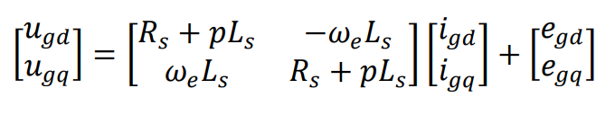
In the synchronous rotation coordinate system, the equation for the voltage on the grid-side converter component is given as:
The output voltage vectors (
us) are
ugd and
ugq, the current vectors (
is) are given as
igd and
igq and the grid voltage vector components of the ds-axis of the converter are
egq and
egd. The grid-side inductance and resistance are
Ls and
Rs,
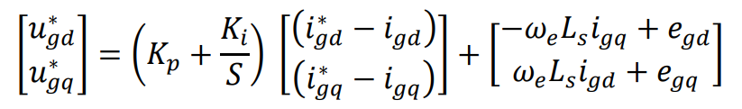
ωe is the angular frequency. To increase the efficacy of the control system, the internal current loop of the grid-side converter implements PI with feedforward decoupling control method in the on-grid. The reference values
ugd and
ugq of grid-connected voltage are produced by inserting the feedforward components of the current
igd, and
igq to compensate
ugd, and
ugq from Equation (6), we have Equation (7).
where
Kp and
Ki are the proportional-integral (PI), and integral gain respectively. The grid voltage vector is expected to correlate with the d-axis of the dq coordinate to accomplish active-reactive power separation in a grid-connected regulator. The do-axis components thus fulfill
egd =
e, and
egq = 0 respectively. The active power (
P) and reactive power (
Q) are:
The grid receives active power when
P is positive, and inductive reactive power when
Q is positive.
5.3. Electrical Energy Storage and Bi-directional Converter
Batteries, supercapacitors, compressed air, superconducting magnetic, and flywheels are all forms of energy storage. However, battery energy storage systems (BESS) are used for the investigation in this paper. The storage systems are coupled to the grids using a bidirectional DC-DC converter. The configuration ensures the charging and discharging of the ESSs. The structure of the bidirectional system with the control is shown in . The converter’s ability to operate in both directions is provided by switches S1 and S2, which are triggered by additional signals from the controller. The operation of switch S1 is for charging when it brings
Vdc on the right side down to
Vb, while the operation of switch S2 is for discharging, which operates during boost mode [
101,
105].
. Bidirectional battery storage system with controller.
From the above figure, the inductor
Lb and capacitor
Cb are given in Equations (10) and (11) respectively.
where
Vdc is the DC-link voltage,
Vd is the battery nominal voltage, inductance ripple current is ∆
iL, and
fs is the switching frequency. Buck and boost converters duty ratio are given in Equations (12) and (13) respectively.
The PI control block is cascaded with the battery current loop to provide the
Ddc duty ratio. Switch S1 and S2 are operated by the PWM, which receives the duty ratio. The duty ratio is defined in Equation (14):
The battery reference current is given as
ib∗,
Pw is the active power reference. The PI controller proportional and integral gains are
Kp and
Ki. The battery state of charge (SOC) is given in Equation (15) [
107,
108].
The battery capacity is
Q and
Ibat is the battery current. The battery charging and discharging depend on the generated power and the energy restriction which are controlled by the SOC limit [
107,
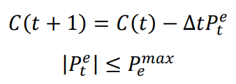
108]. The charge and discharge equation are in Equations (16) and (17):
where
Pte is the battery output power,
Pemax is the maximum charge or discharge rate, total power at time
t is
C(
t), ∆
t is the time interval,
CS stored energy,
Cmin and
Cmax are the minimum and maximum stored energy.
6. Voltage Constraints
The designed system must work synchronously with the existing grid and maintain standard voltage limits. The integration RESs must be complied with the IEEE standards [
111]. Equation (18) defines the allowable voltage fluctuation range for the designed system.
where
Vn is the voltage at buses,
Vmin is the lowest voltage threshold, and
Vmax is the maximum allowable voltage.
In this paper, the minimum and maximum voltage were set to 0.88 pu and 1.1 pu.
depicts the full one-line diagram of the system under investigation connected to a utility low-voltage distribution network via PCC using a circuit breaker.
. Complete a one-line diagram of the system under investigation.
7. Simulation Results Discussion
The paper aimed to assess the performance of the designed systems under various operating conditions. Some of the simulated instances for performance evaluation include stand-alone mode, grid-connected mode, and transition from one mode of operation to another. In each case, normal operation, fault occurrences, increase in power generation, increase in loading system, and sudden de-energized of RESs are some of the simulated and evaluated in each instance.
7.1. Stand-alone Mode of Operation
In this scenario, the utility grid is intentionally decoupled from the microgrid so that both networks supply power to the connected loads independently. In this mode, two cases were simulated and analyzed.
• Case1: Simulation of Normal Operation
The system parameters were simulated without considering any disturbances on the utility and microgrid. The storage systems were set to charging modes. The simulation results are shown in (I–III).
. System performance during normal operation in stand-alone mode. (I) PCC voltage, current, and power; (II) Utility and microgrid voltage and current; (III) Utility and Microgrid energy storage characteristics.
(I) shows the voltage, current, and power (active and reactive) measured at the PCC; (II) depicts the voltage and current measured at some selected buses from the utility grid and MG, and Figure11 (III) shows the utility grid and microgrid battery energy storage characteristics. As indicated in Section 6, the designed system must be operating within the acceptable minimum and maximum voltage ranges of 0.88 pu and 1.1 pu respectively. From (I–III), the systems complied with the maximum and minimum voltage ranges because there were no disturbances, such as faults or changes in the loading system, on the grids.
• Case 2: Simulation of Fault
In this case, the system is subjected to a three-phase fault at line 4 between buses 3 and 4 on the utility grid. (I,II) shows the response of the system at PCC and the selected buses on the utility grid and microgrid during the fault. As can be seen, the fault affected only the utility grid and PCC for a period of 0.08 to 1.12 s. However, the effect of the fault did not spread to the microgrid side, as indicated in (II) microgrid voltage and current.
. Three phase-phase fault at the Utility grid during stand-alone mode: (I) Voltage, current, and power at PCC; (II) Voltage and current at some selected buses on the utility grid and microgrid sides.
The system’s grid-integrated simulation results are presented in this section. The simulated scenarios in this mode of operation include faults, transitions from autonomous mode to grid-connected, increases in total generation on the microgrid, sudden disconnection of a micro-source, and changes in the loading system of the microgrid.
• Scenario 1: Fault occurrence on the utility grid
The system is exposed to a three-phase fault between Bus 5 and 6 on the utility grid. (I,II) shows the performance of the system during the three-phase fault. The voltage, current, and power waveforms at PCC are shown in (I), while (II) shows the response of the utility grid and microgrid to the fault. The fault is set to occur within 0.08 s and 0.12 s on the system, and it was observed that the fault effect spread all over the utility grid and microgrid, as shown in (I,II).
. Three phase-phase fault at the utility grid during grid-connected mode of operation; (I) Voltage, current, and power at PCC, (II) Voltage and current at selected buses on utility and microgrid sides.
• Scenario 2: Transition from Stand-alone to Grid Connected
This section analyzes the sudden transition of the system from grid-connected to stand-alone. (I–III) shows the utility grid response to the scenario, while (III,IV) shows the microgrid performance during the scenario.
. System performance during transition from grid connected to stand-alone mode: (I) PCC and utility grid Bus 5 voltage and current (II) Utility energy storage characteristics (III) Microgrid MGBus 3 Voltage and Current, (IV) Microgrid battery storage waveforms.
To ensure a smooth transition and ensure grid stability, storage systems were activated to support the grid. As can be observed in II, after a few seconds of transition, the utility grid storage system was engaged to deliver extra power to the MG. The upward movement of the SOC indicates the charging mode of the battery, while the downward movement indicates that the battery was discharging, delivering extra supply to the system. To avoid overvoltage on the microgrid side, the utility battery was switched to charging mode, as shown in IV. I shows voltage, current, and powers at PCC during the transition from grid-connected to stand-alone mode of operation. At
t = 0.08 s, the shift from grid-connected to stand-alone mode was activated during this period, and there were occurrences of ripple on the entire system voltage before the system became stable again.
• Scenario 3: Increase in Microgrid Generation
In this case, the small hydropower plant source increases its power generation by 0.9 MW at 0.12 s for almost half a second, after which the storage systems are activated to provide support to the grid. (I–IV) shows the system performance during an increase in microgeneration sources.
. System performance during increases in microgrid generation; (I) PCC voltage current and power; (II) Utility grid energy storage characteristics (III) Utility grid and Microgrid (MGBus 3) Voltage and Current (IV) Microgrid Battery storage characteristics.
The microgrid system experienced overvoltage for the period of for a period of 0.1 s before the storage system was activated, as seen in (III). (I) shows the response of the system at PCC; during the scenario. The active and reactive power increased before the system storage was activated, and the microgrid system also switched to grid-connected mode. To ensure system stability during the increase in power generation, energy storage system switches were energized to charging mode to store the excess power generated, as shown in (II,IV).
• Scenario 4: Change in System Loading
The variations in the system loading are discussed and analyzed in this section. (I,II) shows the performance of the system during an increase in the microgrid loading system, while (I,II) shows the response of the system during a reduction in system loading. The system response to the scenario at PCC is shown in (I). During an increase in microgrid system load, there is a reduction in microgrid voltage and current from 0 s to 0.8 s; on the contrary, the utility grid maintains its normal voltage and current level during the period. At 0.08 s, energy storage systems were activated to discharge mode to provide support to the microgrid; thus, the microgrid system adjusted itself back to normal voltage and current, as can be seen in (II), nevertheless, the microgrid voltage experienced a little ripple. However, the utility grid suffers a reduction in voltage and current scenario; but still operates within the acceptable voltage range of 0.85 pu to 1.0 pu. (I,II) shows the performance of the system during a reduction in the microgrid load.
. System performance during an increase in microgrid load; (I) PCC voltage, Current, and Power; (II) Utility grid and Microgrid voltage and current.
. System performance during a reduction in microgrid loading system; (I) PCC voltage current and power; (II) Utility grid and Microgrid voltage and current.
• Scenario 5: Sudden De-energized of a Micro-source
In this case, the small hydropower plant was suddenly out of service. (I,II) shows the system’s response to the situation. (I) shows single-phase voltage and current at the PCC. As can be seen, the system experiences a voltage and current reduction for a period of 0.1 s when the micro-source is suddenly out of service. Furthermore, (II) shows the utility grid response to the situation; the system experiences voltage and current reduction from the period of the micro-source deactivation. Also, the microgrid experiences voltage sag for the period of 0.08 s to 0.1 s. However, the microgrid was unable to restore to its normal operating condition even though the storage systems were active to support the system, as shown in (II).
. System performance to sudden disconnection of a micro-source from the microgrid; (I) PCC voltage and current (II) Utility grid and microgrid voltage and current.
8. Overview of Microgrid Limitation
The inconsistency of power supply from diverse RESs, like solar and wind, poses a restriction to renewable energy-based MGs. It is also challenging to resynchronize and coordinate the microgrid with the utility grid when the fault on the grid has been cleared. Another limitation to the utilization of microgrids is the implementation of an effective protection mechanism. Furthermore, power quality issues are another limitation of microgrids [
112].
9. Conclusions and Future Works
This paper presents a comprehensive review of MGs and evaluates the system performance when integrated into the low-voltage distribution network, considering different operating scenarios. The paper evaluates the system performance both in grid-connected and island modes of operation. Normal operation, fault analysis, an increase in the generating capacity of microgrids, an increase in system loading, and a sudden loss of energy sources from microgrids are some of the simulated and evaluated cases considered in the paper. In addition, the transition from grid-connected to stand-alone mode, as well as re-synchronization with the main grid, were simulated and analyzed. The simulation results show the performance of the system under various scenarios. In a stand-alone mode of operation, the effect of the fault was only felt on the utility grid for a period of 0.08 to 1.12 s and did not escalate to the microgrid side. However, the fault spread across the network during grid-connected mode. Also, during the transition from grid-connected to stand-alone the system under investigation experiences a voltage rise for the period of transition. However, activation of the storage system to discharge mode brought stability to the system. In addition, during the simulation of the sudden de-energized of a micro-source, the system experienced under-voltage. However, during this scenario, the system was unable to regain its stability even when the storage system was activated to provide support to the grid; this forms part of future work. Generally, power quality issues, grid synchronization, and protection during the transition from one mode of operation to another are some of the challenges identified during the performance evaluation carried out in this paper. It was observed that the effects of the fault escalated throughout the system during fault analysis on either side of the system during grid-connected mode. However, the effectiveness of the storage system for system stability was proven effective. Nevertheless, interconnected microgrid stability, and prevention of power quality issues during disturbances on the grid, at low-voltage distribution networks using power electronic interface are some of the proposed topics for future works. Finally, the paper also reviewed the limitations of microgrid implementation.
Author Contributions
Conceptualization, E.J.A.; Methodology, E.J.A.; Software, E.J.A.; Validation, K.A.O. and E.J.A.; Formal Analysis, E.J.A.; Investigation, E.J.A.; Resources, K.A.O.; Data Curation, K.A.O.; Writing – Original Draft Preparation, E.J.A.; Writing – Review & Editing, E.J.A.; K.A.O; Visualization, K.A.O.; Supervision, K.A.O.
Ethics Statement
Not applicable.
Informed Consent Statement
Not applicable.
Funding
This research received no external funding.
Declaration of Competing Interest
The authors affirmed that they did not know any competing financial interests or personal ties that might have appeared to have an impact on the research presented in this study.
References
1.
United Nations Department of Economic and Social Affairs. World Population Prospects 2022. Available online:
www.un.org/development/desa/pd/ (accessed on 1 July 2022).
2.
Saeed MH, Fangzong W, Kalwar BA, Iqbal S. A Review on Microgrids’ Challenges Perspectives.
IEEE Access 2021,
9, 166502–166517.
[Google Scholar]
3.
Deshmukh MK, Deshmukh SS. Modeling of hybrid renewable energy systems.
Renew. Sustain. Energy Rev. 2008,
12, 235–249.
[Google Scholar]
4.
Canziani F, Vargas R, Gastelo-Roque JA. Hybrid Photovoltaic-Wind Microgrid With Battery Storage for Rural Electrification: A Case Study in Perú.
Front. Energy Res. 2021,
8, 528571.
[Google Scholar]
5.
Mahmud MA, Hossain MJ, Pota HR. Voltage variation on distribution networks with distributed generation: Worst case scenario.
IEEE Syst. J. 2014,
8, 1096–1103.
[Google Scholar]
6.
Chiradeja P, Ramakumar R. An approach to quantify the technical benefits of distributed generation.
IEEE Trans. Energy Convers. 2004,
19, 764–773.
[Google Scholar]
7.
Gil HA, Joos G. Models for quantifying the economic benefits of distributed generation.
IEEE Trans. Power Syst. 2008,
23, 327–335.
[Google Scholar]
8.
Abbey C, Katiraei F, Brothers C, Dignard-Bailey L, Joos G. Integration of distributed generation and wind energy in Canada. In Proceeding of the 2006 IEEE Power Engineering Society General Meeting, Montreal, QC, Canada, 18–22 June 2006.
9.
Katiraei F, Abbey C, Bahry R. Analysis of voltage regulation problem for a 25-kV distribution network with distributed generation. In Proceeding of the 2006 IEEE Power Engineering Society General Meeting, Montreal, QC, Canada, 18–22 June 2006.
10.
Suman GK, Guerrero JM, Roy OP. Robust Frequency Control in Interconnected Microgrids: An H
2/H
∞ Control Approach.
IEEE Syst. J. 2022,
16, 2044–2055.
[Google Scholar]
11.
Hirsch A, Parag Y, Guerrero J. Microgrids: A review of technologies, key drivers, and outstanding issues.
Renew. Sustain. Energy Rev. 2018,
90, 402–411.
[Google Scholar]
12.
Castillo-Calzadilla T, Macarulla AM, O. Kamara-Esteban, Borges CE. A case study comparison between photovoltaic and fossil generation based on direct current hybrid microgrids to power a service building.
J. Clean. Prod. 2020,
244, 118870.
[Google Scholar]
13.
Castillo-Calzadilla T, Cuesta MA, Quesada C, Olivares-Rodriguez C. Is a massive deployment of renewable-based low voltage direct current microgrids feasible ? Converters, protections, controllers, and social approach.
Energy Rep. 2022,
8, 12302–12326.
[Google Scholar]
14.
Castillo-Calzadilla T, Cuesta MA, Olivares-Rodriguez C, Macarulla AM, Legarda J. Is it feasible a massive deployment of low voltage direct current microgrids renewable-based ? A technical and social sight.
Renew. Sustain. Energy Rev. 2022,
161, 112198.
[Google Scholar]
15.
Ton DT, Smith MA. The U.S. Department of Energy’s Microgrid Initiative.
Electr. J. 2012,
25, 84–94.
[Google Scholar]
16.
Parhizi S, Lotfi H, Khodaei A, Bahramirad S. State of the art in research on microgrids: A review.
IEEE Access 2015,
3, 890–925.
[Google Scholar]
17.
Mohammed A, Refaat SS, Bayhan S, Abu-Rub H. AC Microgrid Control and Management Strategies: Evaluation and Review.
IEEE Power Electron. Mag. 2019,
6, 18–31.
[Google Scholar]
18.
Marnay C, Chatzivasileiadis S, Abbey C, Iravani R, Joos G, Lombardi P, et al. Microgrid Evolution Roadmap Engineering, Economics, and Experience. In Proceedings of the 2015 International Symposium on Smart Electric Distribution Systems and Technologies (EDST15), Vienna, Austria, 7–11 September 2015.
19.
Schwaegerl C, Tao L. Quantification of technical, economic, environmental and social benefits of microgrid operation. In Microgrids; John Wiley & Sons, Ltd: Hoboken, NJ, USA, 2013.
20.
Hatziargyriou N, Asano H, Iravani R, Marnay C. An Overview of Ongoing Research, Development, and Demonstration Projects.
IEEE Power Mag. 2007,
5, 78–99.
[Google Scholar]
21.
Peças Lopes JA, Moreira CL, Madureira AG, Resende FO, Wu X, Jayawarna N, et al. Control strategies for MicroGrids emergency operation. In Proceedings of the 2005 International Conference on Future Power Systems, Amsterdam, The Netherlands, 18 November 2005.
22.
Abdi H, Shahbazitabar M. Smart city: A review on concepts, definitions, standards, experiments, and challenges.
J. Energy Manag. Technol. 2020,
4, 1–6.
[Google Scholar]
23.
Abbasi M, Abbasi E, Li L, Aguilera RP, Lu D, Wang F. Review on the Microgrid Concept, Structures, Components, Communication Systems, and Control Methods.
Energies 2023,
16, 484.
[Google Scholar]
24.
Guerrero JM, Chandorkar M, Lee TL, Loh PC. Advanced control architectures for intelligent microgrids-part i: Decentralized and hierarchical control.
IEEE Trans. Ind. Electron. 2013,
60, 1254–1262.
[Google Scholar]
25.
Moran B. Microgrid load management and control strategies. In Proceedings of the 2016 IEEE/PES Transmission and Distribution Conference and Exposition (T&D), Dallas, TX, USA, 3–5 May 2016.
26.
Mbungu NT, Madiba T, Bansal RC, Bettayeb M, Naidoo RM, Siti MW, et al. Economic optimal load management control of microgrid system using energy storage system.
J. Energy Storage 2022,
46, 103843.
[Google Scholar]
27.
Zia MF, Elbouchikhi E, Benbouzid M. Microgrids energy management systems: A critical review on methods, solutions, and prospects.
Appl. Energy 2018,
222, 1033–1055.
[Google Scholar]
28.
Erenoğlu AK, Şengör İ, Erdinç O, Taşcıkaraoğlu A, Catalão JPS. Optimal energy management system for microgrids considering energy storage, demand response, and renewable power generation.
Int. J. Electr. Power Energy Syst. 2022,
136, 107714.
[Google Scholar]
29.
Elsied M, Oukaour A, Gualous H, Hassan R. Energy management and optimization in microgrid system based on green energy.
Energy 2015,
84, 139–151.
[Google Scholar]
30.
Patrao I, Figueres E, Garcerá G, González-Medina R. Microgrid architectures for low voltage distributed generation.
Renew. Sustain. Energy Rev. 2015,
43, 415–424.
[Google Scholar]
31.
Fu Q, Nasiri A, Solanki A, A. Bani-Ahmed, Weber L, Bhavaraju V. Microgrids: Architectures, Controls, Protection, and Demonstration.
Electr. Power Compon. Syst. 2015,
43, 1453–1465.
[Google Scholar]
32.
Hossain E, Kabalci E, Bayindir R, Perez R. Microgrid testbeds around the world: State of art.
Energy Convers. Manag. 2014,
86, 132–153.
[Google Scholar]
33.
Hammerstrom DJ. AC versus DC distribution systems-did we get it right? In Proceedings of the 2007 IEEE Power Engineering Society General Meeting, Tampa, FL, USA, 24–28 June 2007.
34.
Jiang Z, Yu X. Hybrid DC- and AC-linked microgrids: Towards integration of distributed energy resources. In Proceedings of the 2008 IEEE Energy 2030 Conference, Atlanta, GA, USA, 17–18 November 2008.
35.
Ahmed M, Meegahapola L, Vahidnia A, Datta M. Stability and Control Aspects of Microgrid Architectures-A Comprehensive Review.
IEEE Access 2020,
8, 144730–144766.
[Google Scholar]
36.
Venkateswaran VB, Saini DK, Sharma M. Environmental constrained optimal hybrid energy storage system planning for an Indian distribution network.
IEEE Access 2020,
8, 97793–97808.
[Google Scholar]
37.
Iovine A, Rigaut T, Damm G, E. De Santis, Di Benedetto MD. Power management for a DC MicroGrid integrating renewables and storages.
Control Eng. Pract. 2019,
85, 59–79.
[Google Scholar]
38.
Arulampalam A, Barnes M, Engler A, Goodwin A, Jenkins N. Control of power electronic interfaces in distributed generation Microgrids.
Int. J. Electron. 2004,
91, 503–523.
[Google Scholar]
39.
Zhu X, Han XQ, Qin WP, Wang P. Past today and future development of micro-grids in China.
Renew. Sustain. Energy Rev. 2015,
42, 1453–1463.
[Google Scholar]
40.
Justo JJ, Mwasilu F, Lee J, Jung JW. AC-microgrids versus DC-microgrids with distributed energy resources: A review.
Renew. Sustain. Energy Rev. 2013,
24, 387–405.
[Google Scholar]
41.
Shahparasti M, Mohamadian M, Baboli PT, Yazdianp A. Toward power quality management in hybrid AC-DC microgrid using LTC-L utility-interactive inverter: Load voltage-grid current tradeoff.
IEEE Trans. Smart Grid 2017,
8, 857–867.
[Google Scholar]
42.
Hossain MA, Pota HR, Issa W, Hossain MJ. Overview of AC microgrid controls with inverter-interfaced generations.
Energies 2017,
10, 1300.
[Google Scholar]
43.
Alfergani A, Khalil A, Rajab Z. Networked control of AC microgrid.
Sustain. Cities Soc. 2018,
37, 371–387.
[Google Scholar]
44.
Shahgholian G. A brief review on microgrids: Operation, applications, modeling, and control.
Int. Trans. Electr. Energy Syst. 2021,
31, e12885.
[Google Scholar]
45.
Salkuti SR. Challenges, issues and opportunities for the development of smart grid.
Int. J. Electr. Comput. Eng. 2020,
10, 1179–1186.
[Google Scholar]
46.
Arnold GW. Challenges and opportunities in smart grid: A position article.
Proc. IEEE 2011,
99, 922–927.
[Google Scholar]
47.
Che L, Shahidehpour M. DC microgrids: Economic operation and enhancement of resilience by hierarchical control.
IEEE Trans. Smart Grid 2014,
5, 2517–2526.
[Google Scholar]
48.
Planas E, Andreu J, Gárate JI, I. Martínez De Alegría, Ibarra E. AC and DC technology in microgrids: A review.
Renew. Sustain. Energy Rev. 2015,
43, 726–749.
[Google Scholar]
49.
Tavakkoli MA, Radan A, Hassibi H. Simulation and Analysis of a Compact Electronic Infrastructure for DC Micro-Grid: Necessity and Challenges.
Smart Grid Renew. Energy 2012,
3, 73–82.
[Google Scholar]
50.
Zhang F, Meng C, Yang Y, Sun C, Ji C, Chen C, et al. Advantages and challenges of DC microgrid for commercial building: A case study from Xiamen university DC microgrid. In Proceedings of the 2015 IEEE First International Conference on DC Microgrids (ICDCM), Atlanta, GA, USA, 7–10 June 2015.
51.
Dragičević T, Lu X, Vasquez JC, Guerrero JM. DC Microgrids - Part II: A Review of Power Architectures, Applications, and Standardization Issues.
IEEE Trans. Power Electron. 2016,
31, 3528–3549.
[Google Scholar]
52.
Ashok Kumar A, Amutha Prabha N. A comprehensive review of DC microgrid in market segments and control technique.
Heliyon 2022,
8, e11694.
[Google Scholar]
53.
Pires VF, Pires A, Cordeiro A. DC Microgrids: Benefits, Architectures, Perspectives and Challenges.
Energies 2023,
16, 1217.
[Google Scholar]
54.
Kumar J, Agarwal A, Agarwal V. A review on overall control of DC microgrids.
J. Energy Storage 2019,
21, 113–138.
[Google Scholar]
55.
Ding G, Gao F, Zhang S, Loh PC, Blaabjerg F. Control of hybrid AC/DC microgrid under islanding operational conditions.
J. Mod. Power Syst. Clean Energy 2014,
2, 223–232.
[Google Scholar]
56.
Jain D, Saxena D. Comprehensive review on control schemes and stability investigation of hybrid AC-DC microgrid.
Electr. Power Syst. Res. 2023,
218, 109182.
[Google Scholar]
57.
Unamuno E, Barrena JA. Hybrid ac/dc microgrids - Part I: Review and classification of topologies.
Renew. Sustain. Energy Rev. 2015,
52, 1251–1259.
[Google Scholar]
58.
Wang P, Goel L, Liu X, Choo FH. Harmonizing AC and DC: A Hybrid AC/DC future grid solution.
IEEE Power Energy Mag. 2013,
11, 76–83.
[Google Scholar]
59.
Aybar-Mejía M, Villanueva J, Mariano-Hernández D, Santos F, Molina-García A. A review of low-voltage renewable microgrids: Generation forecasting and demand-side management strategies.
Electronics 2021,
10, 2093.
[Google Scholar]
60.
Fregosi D, Ravula S, Brhlik D, Saussele J, Frank S, Bonnema E, et al. A comparative study of DC and AC microgrids in commercial buildings across different climates and operating profiles. In Proceedings of the 2015 IEEE First International Conference on DC Microgrids (ICDCM), Atlanta, GA, USA, 7–10 June 2015.
61.
Manandhar U, Ukil A, Jonathan TKK. Efficiency comparison of DC and AC microgrid. In Proceedings of the 2015 IEEE Innovative Smart Grid Technologies - Asia (ISGT ASIA), Bangkok, Thailand, 3–6 November 2015.
62.
Tan Y, Meegahapola L, Muttaqi KM. A review of technical challenges in planning and operation of remote area power supply systems.
Renew. Sustain. Energy Rev. 2014,
38, 876–889.
[Google Scholar]
63.
Jiang Q, Xue M, Geng G. Energy management of microgrid in grid-connected and stand-alone modes.
IEEE Trans. Power Syst. 2013,
28, 3380–3389.
[Google Scholar]
64.
Micallef A, Apap M, Staines CS, Zapata JMG. Secondary control for reactive power sharing and voltage amplitude restoration in droop-controlled islanded microgrids. In Proceedings of the 2012 3rd IEEE International Symposium on Power Electronics for Distributed Generation Systems (PEDG), Aalborg, Denmark, 25–28 June 2012.
65.
Marinescu C, Serban I. Robust frequency control for a wind/hydro autonomous microgrid. In Proceedings of the 2011 IEEE Trondheim PowerTech, Trondheim, Norway, 19–23 June 2011.
66.
Pedrasa MA, Spooner T. A Survey of Techniques Used to Control Microgrid Generation and Storage during Island Operation. In Proceedings of the 16th Australasian Universities Power Engineering Conference (AUPEC2006), Melbourne, VIC, Australia, 10–13 December 2006.
67.
Kaushal J, Basak P. A Decision-Making Methodology to Assess Power Quality Monitoring Index of an AC Microgrid Using Fuzzy Inference Systems.
Electr. Power Compon. Syst. 2019,
47, 1349–1361.
[Google Scholar]
68.
Falahi M, Butler-Purry KL, Ehsani M. Induction motor starting in islanded microgrids.
IEEE Trans. Smart Grid 2013,
4, 1323–1331.
[Google Scholar]
69.
Wu D, Wu H, Dongt H. Influence of induction motor starting on microgrid. In Proceedings of the 2018 IEEE PES Asia-Pacific Power and Energy Engineering Conference (APPEEC), Kota Kinabalu, Malaysia, 7–10 October 2018.
70.
Choudhury S. A comprehensive review on issues, investigations, control and protection trends, technical challenges and future directions for Microgrid technology.
Int. Trans. Electr. Energy Syst. 2020,
30, e12446.
[Google Scholar]
71.
Azeem O, Ali M, Abbas G, Uzair M, Qahmash A, Algarni A, et al. A comprehensive review on integration challenges, optimization techniques and control strategies of hybrid ac/dc microgrid.
Appl. Sci. 2021,
11, 6242.
[Google Scholar]
72.
Murakami T. Agent-based simulations of the influence of social policy and neighboring communication on the adoption of grid-connected photovoltaics.
Energy Convers. Manag. 2014,
80, 158–164.
[Google Scholar]
73.
Kumar A, Singh AR, Deng Y, He X, Kumar P, Bansal RC. Integrated assessment of a sustainable microgrid for a remote village in hilly region.
Energy Convers. Manag. 2019,
180, 442–472.
[Google Scholar]
74.
Kumar A, Singh AR, Deng Y, He X, Kumar P, Bansal RC. A Novel Methodological Framework for the Design of Sustainable Rural Microgrid for Developing Nations.
IEEE Access 2018,
6, 24925–24951.
[Google Scholar]
75.
Singh R, Bansal RC, Singh AR, Naidoo R. Multi-Objective Optimization of Hybrid Renewable Energy System Using Reformed Electric System Cascade Analysis for Islanding and Grid Connected Modes of Operation.
IEEE Access 2018,
6, 47332–47354.
[Google Scholar]
76.
Gopakumar P, Reddy MJB, Mohanta DK. Letter to the editor: Stability concerns in smart grid with emerging renewable energy technologies.
Electr. Power Compon. Syst. 2014,
42, 418–425.
[Google Scholar]
77.
Gaur P, Singh S. Investigations on Issues in Microgrids.
J. Clean Energy Technol. 2017,
5, 47–51.
[Google Scholar]
78.
Rathor SK, Saxena D. Energy management system for smart grid: An overview and key issues.
Int. J. Energy Res. 2020,
44, 4067–4109.
[Google Scholar]
79.
Panda S, Mohanty S, Rout PK, Sahu BK, Parida SM, Kotb H, et al. An Insight into the Integration of Distributed Energy Resources and Energy Storage Systems with Smart Distribution Networks Using Demand-Side Management.
Appl. Sci. 2022,
12, 8914.
[Google Scholar]
80.
Rafique SF, Jianhua Z. Energy management system, generation, and demand predictors: A review.
IET Gener. Transm. Distrib. 2018,
12, 519–530.
[Google Scholar]
81.
Xia Y, Peng Y, Yang P, Yu M, Wei W. Distributed Coordination Control for Multiple Bidirectional Power Converters in a Hybrid AC/DC Microgrid.
IEEE Trans. Power Electron. 2017,
32, 4949–4959.
[Google Scholar]
82.
Yang P, Xia Y, Yu M, Wei W, Peng Y. A Decentralized Coordination Control Method for Parallel Bidirectional Power Converters in a Hybrid AC-DC Microgrid.
IEEE Trans. Ind. Electron. 2018,
65, 6217–6228.
[Google Scholar]
83.
Li YW, Vilathgamuwa DM, Loh PC. A grid-interfacing power quality compensator for three-phase three-wire micro-grid applications. In Proceedings of the 2004 IEEE 35th Annual Power Electronics Specialists Conference, Aachen, Germany, 20–25 June 2004; pp. 2011–2017.
84.
Vinayagam A, Swarna KSV, Khoo SY, Oo AT, Stojcevski A. PV Based Microgrid with Grid-Support Grid-Forming Inverter Control-(Simulation and Analysis).
Smart Grid Renew. Energy 2017,
8, 1–30.
[Google Scholar]
85.
Muhammad T, Khan AU, Chughtai MT, Khan RA, Abid Y, Islam M, et al. An Adaptive Hybrid Control of Grid Tied Inverter for the Reduction of Total Harmonic Distortion and Improvement of Robustness against Grid Impedance Variation.
Energies 2022,
15, 4724.
[Google Scholar]
86.
Anttila S, Döhler JS, Oliveira JG, Boström C. Grid Forming Inverters: A Review of the State of the Art of Key Elements for Microgrid Operation.
Energies 2022,
15, 5517.
[Google Scholar]
87.
Farrokhabadi M, Claudio A, Simpson-Porco JW, Nasr E, Fan L, Mendoza-Araya PA. Microgrid Stability Definitions, Analysis, and Examples.
IEEE Trans. Power Syst. 2020,
35, 13–29.
[Google Scholar]
88.
Mirsaeidi S, Said DM, Mustafa MW, Habibuddin MH, Ghaffari K. Review and analysis of existing protection strategies for micro-grids.
J. Electr. Syst. 2014,
10, 1–10.
[Google Scholar]
89.
Srivastava C, Tripathy M. DC microgrid protection issues and schemes: A critical review.
Renew. Sustain. Energy Rev. 2021,
151, 111546.
[Google Scholar]
90.
Alkahtani AA, Alfalahi STY, Athamneh AA, Al-Shetwi AQ, Mansor MB, Hannan MA, et al. Power Quality in Microgrids including Supraharmonics: Issues, Standards, and Mitigations.
IEEE Access 2020,
8, 127104–127122.
[Google Scholar]
91.
Bayindir R, Hossain E, Kabalci E, Billah KMM. Investigation on north American microgrid facility.
Int. J. Renew. Energy Res. 2015,
5, 558–574.
[Google Scholar]
92.
Prabhakaran K, Chitra N, Kumar AS. Power quality enhancement in microgrid - A survey. In Proccedings of the 2013 International Conference on Circuits, Power and Computing Technologies (ICCPCT), Nagercoil, India, 20–21 March 2013; pp. 126–131.
93.
Pena R, Clare JC, Asher GM. Doubly fed induction generator using back-to-back PWM converters and its application to variable speed wind-energy generation.
IEE Proc. Electr. Power Appl. 1996,
143, 231–241.
[Google Scholar]
94.
Jadidi S, Badihi H, Zhang Y. Passive fault-tolerant model predictive control of AC/DC PWM converter in a hybrid microgrid.
IFAC-PapersOnLine 2020,
53, 12097–12102.
[Google Scholar]
95.
Kumar D, Chatterjee K. Design and analysis of artificial bee-colony-based MPPT algorithm for DFIG-based wind energy conversion systems.
Int. J. Green Energy 2017,
14, 416–429.
[Google Scholar]
96.
Raju AB, Femandes BG, Chatterjee K. Modeling and simulation of a grid-connected variable speed wind energy conversion system with low-cost power converters.
Renew. Energy Power Qual. J. 2003,
1, 97–102.
[Google Scholar]
97.
Yoo CH, Chung IY, Lee HJ, Hong SS. Intelligent control of battery energy storage for multi-agent based microgrid energy management.
Energies 2013,
6, 4956–4979.
[Google Scholar]
98.
Sachdev HS, Akella AK, Kumar N. Analysis and evaluation of small hydropower plants: A bibliographical survey.
Renew. Sustain. Energy Rev. 2015,
51, 1013–1022.
[Google Scholar]
99.
Okot DK. Review of small hydropower technology.
Renew. Sustain. Energy Rev. 2013,
26, 515–520.
[Google Scholar]
100.
Sami I, Ullah N, Muyeen SM, Techato K, Chowdhury S, Ro JS. Control Methods for Standalone and Grid Connected Micro-Hydro Power Plants with Synthetic Inertia Frequency Support: A Comprehensive Review.
IEEE Access 2020,
8, 176313–176329.
[Google Scholar]
101.
Chhipą AA, Chakrabarti P, Bolshev V, Chakrabarti T, Samarin G, Vasilyev AN, et al. Modeling and Control Strategy of Wind Energy Conversion System with Grid-Connected Doubly-Fed Induction Generator.
Energies 2022,
15, 6694.
[Google Scholar]
102.
Parish O. Small hydro power: Technology and current status.
Renew. Sustain. Energy Rev. 2002,
6, 537–556.
[Google Scholar]
103.
Walczak N. Operational evaluation of a Small Hydropower Plant in the context of sustainable development.
Water 2018,
10, 1114.
[Google Scholar]
104.
Gil-González W, Montoya OD, Garces A. Modeling and control of a small hydro-power plant for a DC microgrid.
Electr. Power Syst. Res. 2020,
180, 106104.
[Google Scholar]
105.
Smieee MA, Garmat A, Popescu D, Zidi S, Mazouz L. Modeling and control of wind energy conversion system. In Proceedings of 2016 5th International Conference on Systems and Control (ICSC), Marrakesh, Morocco, 25–27 May 2016.
106.
Hu X, Wang T, Chen K, Ye P, Zhang L. Research on the control system for improving the grid-connected efficiency of small hydropower.
Energy Rep. 2023,
9, 772–783.
[Google Scholar]
107.
Khan SU, Mehmood KK, Haider ZM, Bukhari SBA, Lee S-J, Rafique MK, et al. Energy management scheme for an EV smart charger V2G/G2V application with an EV power allocation technique and voltage regulation.
Appl. Sci. 2018,
8, 648.
[Google Scholar]
108.
Kisacikoglu MC, Ozpineci B, Tolbert LM. EV/PHEV bidirectional charger assessment for V2G reactive power operation.
IEEE Trans. Power Electron. 2013,
28, 5717–5727.
[Google Scholar]
109.
Chen SX, Gooi HB, Wang MQ. Sizing of energy storage for microgrids.
IEEE Trans. Smart Grid 2012,
3, 142–151.
[Google Scholar]
110.
Prabhakaran K, Srividhya R, Senthil Kumar R, Hemanth Kumar D, Mohan Raj D, Sham Prabu A. Energy Management System for Small-Scale Hybrid Wind Solar Battery-Based Microgrid. In EAI/Springer Innovations in Communication and Computing; Springer Nature: Berlin, Germany, 2022.
111.
Read WS. IEEE Standards.
IEEE Power Eng. Rev. 1995,
15, 6–7.
[Google Scholar]
112.
Davison MJ, Summers TJ, Townsend CD. A review of the distributed generation landscape, key limitations of traditional microgrid concept & possible solution using an enhanced microgrid architecture. In Proceeding of the 2017 IEEE Southern Power Electronics Conference (SPEC), Puerto Varas, Chile, 4–7 December 2017.