
A Distributed Framework for Persistent Wildfire Monitoring with Fixed Wing UAVs

Author Information
Other Information
1
Applied Mechanics Lab, University of Patras, 26504 Patras, Greece
2
Department of Aerospace Science & Technology, National Kapodistrian University of Athens, 10563 Athens, Greece
*
Authors to whom correspondence should be addressed.
Received: 17 June 2024 Accepted: 23 July 2024 Published: 25 July 2024

© 2024 The authors. This is an open access article under the Creative Commons Attribution 4.0 International License (https://creativecommons.org/licenses/by/4.0/).
Views:3383
Downloads:375
Drones Veh. Auton.
2024,
1(3), 10009;
DOI: 10.35534/dav.2024.10009
ABSTRACT:
Wildfires
have proven to be a significantly exigent issue over the past decades. An
increasing amount of research has recently been focused on the use of Unmanned
Aerial Vehicles (UAVs) and multi-UAV systems for wildfire monitoring. This work
focuses on the development of a decentralized framework for the purpose of
monitoring active wildfires and their surrounding areas with fixed wing UAVs. It
proposes a distributed fire data update methodology, a new formation algorithm
based on virtual forces, fine-tuned by a Genetic Algorithm (GA), to arrange
virtual agents into the monitoring area, and a control strategy to safely and
efficiently guide fixed wing UAVs to loiter over the structured virtual agents.
The system is tested in Software In The Loop (SITL) simulation with up to eight
UAVs. The simulation results demonstrate the effectiveness of the system in
monitoring the fire in a persistent manner and providing updated situational
awareness data. The experiments show that the proposed framework is able to
achieve and maintain coverage up to 100% over the area of interest, and very
accurate fire representation. However, the performance is decreased for the
experiments with low UAV numbers and large fire sizes.
Keywords:
UAVs;
Fixed wing; Wildfire monitoring; Wildfire coverage; Distributed monitoring
1. Introduction
Wildfires have proven to be a significantly exigent issue over the past decades. Monitoring wildfires is a highly demanding task since it requires accessing remote areas under dangerous conditions. Most forest firefighting missions are designed by firefighting experts based on visual observation of the fire. However, visual observations are prone to human inaccuracies and do not provide complete monitoring of the fire, causing catastrophic results [1]. Collecting real-time information on an active wildfire has proven to be significantly helpful for fire management and extinction. Persistent monitoring of an active fire in its early stages can generate information about the fire spread, which may be crucial for fire containment and extinction. Fires are a dynamic phenomenon, rapidly changing in size and shape. Therefore, it is of high importance to monitor them closely and respond rapidly.
Unmanned Aerial Vehicles (UAVs) are expected to be significantly beneficial in monitoring fires [2]. They are capable of flying in remote and hard-to-reach areas under dangerous conditions. Furthermore, they can be deployed and reach the area of interest in a short time. The employment of UAVs in the management of wildfires contributes to providing firefighters with accurate and real-time data. This empowers them to make prompt decisions and formulate strategic plans for containing and suppressing fires. The UAVs’ ability to monitor fire boundaries and detect hotspots proves invaluable in improving situational awareness and supporting firefighting efforts [3]. The use of swarms of autonomous UAVs significantly augments the capabilities of a single UAV, allowing for large area coverage, improving performance, and decreasing the time required for task completion [4]. The benefits of swarms of UAVs are unlocked only when the agents of the swarm are governed by decentralized and intelligent control that provides autonomy and collaboration capabilities. Fixed wing UAVs offer higher wind resistance and increased flight endurance, two parameters crucial for most wildfire-related tasks. The time elapsed from discovery to control of a wildfire could be several hours or days.
This work presents a framework for monitoring the boundaries and the surrounding area of wildfire by a team of fixed wing UAVs. The system is designed to be distributed with each UAV maintaining a local situational picture of the fire. The UAVs monitor the fire by loitering in a safe and synchronized manner over virtual agents constructing a formation around the fire. The main contributions of this work are summarized here:
- A local fire representation and situational awareness updates, specifically designed for distributed systems is presented.
- A virtual agent formation methodology based on virtual forces and fine-tuned by a Genetic Algorithm (GA) is proposed based on the requirements of monitoring the surroundings of the fire.
- A complete system for efficient and safe formation of fixed wing UAVs around a wildfire based on the positions of virtual agents is described and evaluated.
2. Related Work
Numerous studies have focused on UAV applications for fire search, detection, monitoring, and tracking. Most studies investigate multi-UAV systems since the size of a wildfire is usually too large to be covered by a single UAV [5]. Fire monitoring involves dangerous and long missions, during which the size of the team changes due to failures or recharging [6].
In centralized fire monitoring systems, the UAVs are coordinated by a ground base station, acting as a central entity. UAVs equipped with cameras to detect fire and generate local fire maps are organized in a centralized architecture in [7]. The local fire maps are sent to the ground base, and they are merged into a global fire map by a centralized agent. It is proposed that the centralized agent be equipped with fire propagation estimation software to predict the fire spread. The predicted wildfire map is used by the centralized agent to generate observation trajectories for the UAVs, to monitor the fire perimeter, using a newly introduced planning algorithm inspired by the Variable Neighborhood Search. A simple centralized approach is presented in [8]. The ground station segments the surveillance region and assigns waypoints to the UAVs to scan the area. When one UAV detects fire, the remaining UAVs approach the area to confirm the fire. The inclusion of a centralized agent in imperative roles of the system makes the systems prone to single point of failure problems.
Most researchers focus on distributed implementations since they provide lower communication constraints, higher scalability, and reliability [3]. Artificial Potential Fields (APFs) have been used in numerous variations for decentralized fire monitoring and tracking. Depending on the defined objectives APFs may be adjusted to produce the desired behavior. For example, APFs have been optimized to maximize the fire boundary coverage and minimize the UAVs’ energy consumption [9]. In another case, APFs were used to guide the UAVs toward the areas with the larger heat intensity variation, to prioritize the coverage of the fire front, and away from the other UAVs, to prevent collisions [10]. Furthermore, APFs in [11] have been used to generate a formation based on two criteria: (1) minimize the distance to the fire boundary, and (2) uniformly distribute the UAVs. The UAVs are guided to an elliptic formation around the fire and adjust their intervehicle distances using an artificial potential function.
If the number of available UAVs is lower than the required number to monitor the fire front by hovering, UAVs are tasked to circumnavigate the fire perimeter. A coordination strategy for fire perimeter tracking, focusing on minimizing the latency of update messages to the base station while considering information uncertainties, is required when the communication range is insufficient. The authors of [2] described a strategy in which the UAVs fly in pairs with opposing directions and synchronize at rendezvous points. The proposed distributed strategy adjusts the rendezvous locations of the UAVs with no information on the fire perimeter length.
Future UAV systems for fire monitoring will require the UAVs to be capable of performing both fire search and fire monitoring while coordinating with other UAVs. Searching and tracking are defined as separate modes between which the UAVs transition based on their current understanding of their situation. When no fire is detected, the UAVs are in the search mode, scanning the area of interest. Once a fire is detected, the UAVs transit to a tracking mode. The detected fire announcement/notification may be communicated by a UAV to its neighbors as proposed in [12] to concentrate a sub-team of the UAVs over the detected fire, or directly to a ground station and await to receive a fire tracking trajectory [13].
Although quadcopter UAVs are vastly more popular for fire monitoring tasks, fixed wing UAVs offer higher flight altitudes, much better flight time, and wind resistance. Most research studies focus on the use of quadcopter UAVs for fire monitoring tasks or assume holonomic kinematic models. However, the significant advantages of using fixed wing UAVs for such tasks should drive more researchers to investigate fire monitoring systems to obey non-holonomic constraints. A fault-tolerant time-varying control scheme for fixed wing UAVs is studied in [4]. Sliding-mode disturbance observers were proposed to bind the tracking error of UAV formation while circumnavigating the fire on an elliptical formation. Nevertheless, this work does not address the fire data updates based on UAV observations.
In mixed teams of quadcopter and fixed wing UAVs, different types of UAVs are assigned different roles [14]. Fixed wing UAVs are considered coalition leaders, and quadcopters are coalition followers. The area to be monitored is divided into circular sectors by the fixed wing UAVs using a greedy approach, and each coalition leader “recruits” followers to monitor its assigned sector by hovering at a circle point with the maximum separation from the members of the coalition. This work focused on the resource assignment problem for coalition formation and did does not investigate guidance and control methodologies to execute the required tasks.
Fire detection via thermal, electrooptical, and infrared cameras has been studied in depth in the literature. RGB visual images are often used for the detection of fire smoke via Neural Network (NN) approaches [15]. On the other hand, some works propose the use of traditional computer vision techniques for the fire detection task with optical cameras. Image processing methods for detecting forest fires from RGB camera frames collected by a UAV utilize image preprocessing for noise reduction and color-based decision rules [16,17]. The authors of [18] described a deep learning-based methodology for fire and smoke detection by a combination of optical and thermal video data. Thermal, electrooptical, and infrared cameras may be used in parallel to increase the accuracy of the detection. For example, a framework for fire detection, localization, and diagnosis is described in [19], which fuses the ignition and burning probabilities as estimated by thermal, electrooptical, and infrared sensors.
3. Problem Statement
Given an area of interest with an active wildfire, fixed wing UAVs are tasked to provide persistent coverage over the area. The UAVs must select optimal positions, generating a formation, to loiter over in order to provide full coverage in the area surrounding the fire, prioritizing regions closer to the fire boundaries. To achieve this, each UAV assumes a dynamic virtual agent, moving on the 2D plane, over which the UAV loiters. The area of interest is discretized into a grid of cells. Each cell is a square of dimensions cell size x cell size.
We assume a set of n homogeneous fixed wing UAV agents and a rectangular area of interest centered on the point where the fire was initialized. The UAVs are assumed to know their position perfectly (assuming that they are equipped with GPS devices) and are equipped with downward-facing cameras attached to a gimbal to maintain vertical orientation towards the horizontal plane. Each camera has a rectangular Field Of View (FOV) defined by the horizontal and vertical angles of the sensor and the flight altitude of the UAV. The UAVs are capable of detecting and localizing fire in the camera frames. Additionally, the UAVs carry thermometers to detect extreme heat produced by the fire, which may cause damage to the vehicle. Finally, we assume that the UAV can maintain communication and exchange collected fire data with all other UAVs during the mission at a predetermined rate, while they exchange positioning data with neighboring UAVs at a higher rate.
3.1. UAV Kinematics
The kinematic model of the fixed wing UAVs studied in this work is given by:
where x, y are the position coordinates of the UAV, vgs is the ground speed, $$\varphi$$ is the heading, and ω is the turn rate. The vgs and ω values are limited by the design of the UAV platform.
3.2. UAV Coverage
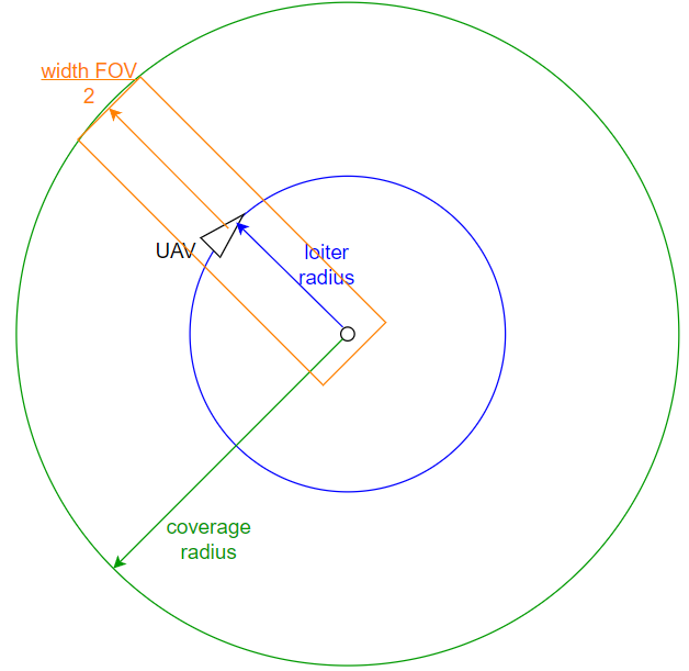
Once the formation algorithm has converged, the UAVs loiter over static positions. In order to provide full coverage over the loitering area the loiter radius of the UAV must be smaller than half the width of the camera’s FOV. As shown in Figure 1, during a full rotation the UAV covers a circular area with a radius of:
where rl is the loitering radius of UAV, and widthfov is the width of the camera’s FOV calculated as:
where alt is the flight altitude of the UAV and camanglehor is the horizontal angle of the camera sensor. As an example, let us assume camanglehor = 1.047 rad, and a flight altitude of 300 m, then the FOV has a width of 305.65 m, and the ideal loiter radius to maximize the coverage is selected at 150 m (the loiter radius is selected to be slightly lower than the maximum allowed value of 152.8 m), resulting in a coverage radius of 302.8 m.
3.3. Wildfire Model
Modeling of wildfires and their spreading has attracted significant research interest in an attempt to predict the behavior and spreading of wildfires [10]. Numerous simulation models have been proposed considering the geospatial information of the area, the vegetation, and the weather conditions. Achieving an accurate fire spread model is out of the scope of this work. Hence, a simplified version of the cellular automata fire spread model has been used.
Cellular automata models handle a finite number of identical elements, called cells. Each cell assumes a state from a discrete set of states. The states of the cells evolve over time based on local transitions. For a fire spread model, the region is discretized into a grid and each cell may be in one of the following states: (1) Burned, (2) Burning, (3) Burnable, (4) Non-burnable.
At each simulation time step the state of each cell is updated based on the following rules:
3.4. Fire Representation
Each UAV of the system maintains a local copy of the map of the area representing the fire. This fire map is built based on the collected information about the fire and is updated during the mission. It provides a representation of the fire to be used for the formation generation. The fire map is based on the grid of cells, with each cell being defined by its position in the grid and a Boolean variable indicating if the cell is considered to be on fire or not. If a cell is flagged to be on fire and at a later point the cell is not on fire, because it burned, the state of the cell does not change in the fire map. Therefore, burning and burned cells are treated the same in the fire representation.
In addition to the fire map, each UAV maintains a fire augmentation map and a virtual agent area map. The fire augmentation map indicates cells that are in so close proximity to the fire that the UAV is vulnerable to damage caused by the fire. The fire is augmented based on the loiter radius rl of the UAV, as to ensure that if the virtual agent of the UAV is outside of the augmented fire, the UAV loitering over it, will not fly over fire. On the other hand, the virtual agent area map draws the area limits within which the virtual agents must be placed to provide coverage to the area around the fire. A monitoring distance dmon is used to define the inflated polygon around the fire that the system is tasked to monitor. Virtual agents placed in any location outside the fire and at a distance to the closest fire cell smaller than dmon + rcov can provide useful coverage. Therefore, the virtual agent area map marks all the cells, that are not on fire, with a distance smaller than dmon + rcov to any cell with fire.
Finally, the monitoring area map is introduced. Although this map is not computed by the UAVs and is not used for the proposed system’s execution, it is used for the evaluation of the system. It describes the area that we are interested in monitoring with a higher priority given to cells with close proximity to fire cells. Instead of using a Boolean variable like the rest of the maps introduced here, it assigns a priority to each cell depending on the importance of collecting information from that cell. The cells closest to the fire have a priority of 1, all the cells, which are not on fire, with a distance smaller than dmon to any cell with fire have a priority of 0.2, and the remaining cells have a priority of 0.0. Figure 3 presents grayscale visualizations of each type of map for the same instance of a fire.
```latex\dot{x}=v_{gs}\times\cos{(\varphi)}\\\dot{y}=v_{gs}\times\sin{(\varphi)},\\\dot{\varphi}=\omega ```
```latexr_{cov}=r_{l}+\frac{width_{fov}}{2},\mathrm{assuming~that~}\frac{width_{fov}}{2}>r_{l},```
```latexwidth_{fov}=2\times alt\times\tan{(\frac{camangle_{hor}}{2})},```
- Burned and non-burnable cells retain their states;
- Burning cells spread the fire to neighboring cells with a probability of pspread depending on the characteristics of both cells;
- Cells that were burning in the previous time step become burned.
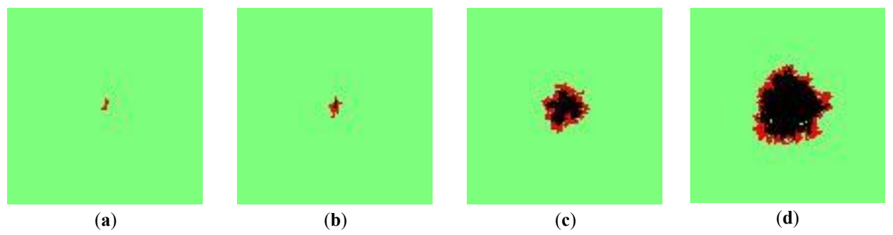
Figure 2. The fire spreading at different time steps of the simulation. (<b>a</b>) Time step 50, (<b>b</b>) Time step 100, (<b>c</b>) Time step 300, (<b>d</b>) Time step 500.
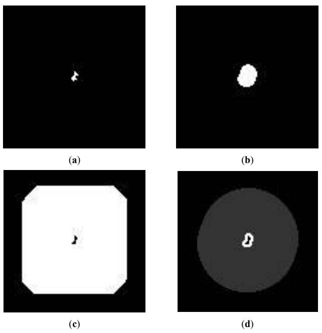
Figure 3. Examples of the four types of maps as grey scale images. (<b>a</b>) The fire map, with the fire depicted in white, (<b>b</b>) The fire augmentation map, with the augmented fire depicted in white, (<b>c</b>) The virtual agent area map, with the virtual agent area depicted in white, (<b>d</b>) The monitoring area map, with the cells with highest priority (of 1) depicted in white, and the cells with lower priority (of 0.2) depicted in grey.
4. System Overview
The main actors of the proposed system are fixed wing UAVs capable of covering and monitoring wildfires based on a distributed approach. However, a ground base is assumed to provide the original mission to the UAVs. It is assumed that the ground base has an original and updated fire representation of the fire spread in its early stages. It shares the original fire map with all involved UAVs and commands them to perform the fire monitoring mission. The role of the ground base is isolated in this pre-mission stage.
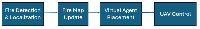
Once they have received the command and fire map, the UAVs start deploying toward the fire, each UAV includes to following software modules to accomplish its mission:
1. Sensor processing software to detect and localize fire in its camera frame.
2. A fire map update software to update its local fire map once new fire data is received.
3. A virtual agent placement algorithm to generate the desired formation around the fire.
4. A UAV control strategy to guide safely the UAV to loiter over its virtual agent and synchronize its phase with neighboring UAVs.
Fire detection and localization are out of the scope of this work, it is therefore assumed that the UAVs are capable of conducting this process. The rest of the methods are presented in the next Section. The modules are executed sequentially in each time step as shown in Figure 4.
During the mission, the UAVs exchange two types of messages:
1. Fire update data: This message is sent when the state of an observed cell has changed (i.e., if a cell flagged as not to be on fire, now is observed to be on fire). The message originates from the UAV which observed the change and is received by all UAVs of the system.
2. Virtual agent and UAV state data: This message is sent at a predefined rate constantly. It includes the position of the virtual agent of the UAV and the position and velocity state of itself. This message is received by all neighboring UAVs within a predefined range.
5. Materials and Methods
This section presents the designed and implemented methods to provide fire monitoring by generating the virtual agent formation and guiding the fixed wing UAVs to orbit their virtual agents in a synchronized and safe manner.
5.1. Fire Map Update
Upon receiving an update for the fire data, each UAV updates its own local representation of the fire map, by updating the fire flags to True or False based on the received data. While the fire map is updated a list of all updated cells is maintained and contains the indices of cells which changed their status in the last iteration. This is used for the update of the fire augmentation and virtual agent area maps.
Based on their definition, the fire augmentation and virtual agent area maps are generated based on the fire cells. Each cell of the fire augmentation map is set to True if the corresponding cell of the fire map is True, or if too close to one or more fire cells. The goal is for UAVs to avoid flying over active fire. Hence, the virtual agents must be placed around the fire at a distance larger than the loiter radius rl to the closest fire cell. To check the distance of a cell to the fire, a kernel is applied to the map. Kernels or convolution matrices are common filters used in image processing. Since the desired maps are 2D arrays, they may be treated as images. The proposed kernel has a circular shape:
The size of the kernel depends on the distance from the fire boundaries that each map represents, and this distance is divided by the size of the cells to be translated into the inter-cell distance. For the fire augmentation map the used inter-cell distance is $$\frac{r_{l}}{cell \,size}+1$$, while for the virtual agent area map it is $$\frac{d_{mon}+r_{cov}}{cell \,size}$$. The value of each cell of the fire augmentation and virtual agent area maps is computed by applying the corresponding kernel to the fire map, centered at the regarding cell. If the convolution returns any value equal to or larger than 1.0, it means that the cell has a fire cell within the distance defined by each map, and the cell is set to True.
The update of the fire augmentation and virtual agent area maps does not necessarily imply the computation of the overall map. If the updated cells are all concentrated in a region of the map, only the cells with a distance of half the corresponding kernel size will be affected.
5.2. Virtual Agent Placement
Let us assume that qi(t) represents the 2D position of the virtual agent i in the horizontal plane. Each UAV initializes its virtual agent relative to each current position and heading (yawi) at:
Afterward, the qi(t) is updated based on the formation algorithm described below. If at any point during the mission, the distance between the UAV and its virtual agent exceeds a threshold distance the virtual agent is initialized again relative to the UAV. The virtual agent is assumed to be holonomic.
The main objective of the proposed formation algorithm is to maximize the coverage provided by all the UAVs of the system, in the area around the fire, prioritizing areas closer to the fire boundaries. For this purpose, a formation algorithm is designed, in which the virtual agents update their positions based on virtual forces acting upon them from the fire representation and from other virtual agents. After the virtual forces and the position update logic were designed their constants were fine-tuned via a genetic algorithm.
5.2.1. Virtual Force Towards the Fire
This is an attractive force applied to virtual agents towards the fire. Its purpose is to concentrate the virtual agents closer to the fire and the area around the fire to cover the area indicated by the monitoring area map. It is calculated as:
where qf is the position of the center of the fire, dif is the Euclidean distance between qf and qi and c1, c2 are tunable constants. The center of the fire is computed as the center of gravity of the fire map.
5.2.2. Virtual Formation Force
This is a repulsive force acting between virtual agents. Its purpose is to generate and maintain a uniform distribution formation of the virtual agents, to collectively cover the largest area possible. The virtual formation force is designed to generate a triangular lattice topology, as presented in [22]. It is calculated as:
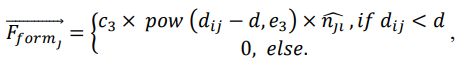 where V is the set of virtual agents, corresponding to UAVs within rcom distance, $$\widehat{n_{jl}}$$ is the normalized vector from virtual agent j to virtual agent i, and c3, e3 are tunable constants.
5.2.3. Virtual Force Avoiding Fire
This is a repulsive force from the fire towards the virtual agents. Its purpose is to maintain a safety distance between the active fire and the UAVs. It is calculated as:
where c4 is a tunable constant.
5.2.4. Position Update
After the virtual forces described above have been computed the resultant force is computed as:
which can be analyzed to the x, y axis of the horizontal plane as:
A tunable threshold value of t1 is used to ignore weak force values of $$\vec{F}$$, this threshold is applied to avoid unnecessary oscillations, which would delay the algorithm’s convergence. Afterward, the magnitude of $$\vec{F}$$ is normalized to the maximum allowed velocity velmax, and the position of the virtual agent is updated as:
5.2.5. Local Minima
The described formation method uses virtual forces and shares commonalities with APFs methods. A major and common drawback of APFs is local minima. When under the influence of virtual forces an agent may experience a very small or zero resultant force without having reached an optimal position. A customary solution for the local minima problem is to detect local minima situations and enforce an escape strategy.
Therefore, after the resultant force $$\vec{F}$$ has been computed, an additional step is conducted to check for local minima and resolve them. The virtual agent is assumed to be stuck in a local minima if $$\left|\vec{F}\right| < t_1$$ and $$|\overrightarrow{F_{form}}|>t_2$$, where t1 is the tunable threshold to ignore weak forces and t2 is a tunable threshold for formation force. If a local minima is detected, an escape force $$\overrightarrow{F_{esc}}$$ is applied to the virtual agent, calculated as:
where c5 is a tunable constant, and $$\widehat{n_{\iota f_{ver}}}$$ is the normalized vector vertical to the vector connecting the virtual agent to the center of the fire. This virtual escape force aims to guide the virtual agent to a conical trajectory centered at the center of the fire. Hence, the virtual agent will explore other regions of the monitoring area.
5.2.6. Constant Tuning
The formation algorithm described in the current section uses a set of six constants and two thresholds. The performance of the system depends on the selection of proper values for those. In order to optimize the selected values, a Genetic Algorithm was implemented and used. In literature, GAs have been used to solve various optimization problems in different domains.
GAs are inspired by biological evolution and natural selection. They use a population-based approach, in which potential solutions are represented as chromosomes. Each chromosome is evaluated by a fitness function to quantify the optimality of the solution. GAs are iterative methods, and each iteration is referred to as generation. The best performing chromosomes of each generation are used to produce the next generation.
In this work, a GA is used to select the best performing values for the set of constants: $$\{c_1,c_2,c_3,c_4,c_5,e_3,t_1,t_2\}$$ used in the formation algorithm. Therefore, the chromosome is defined as a list of eight genes, each representing one of the constants to be tuned. Each of these constants is bounded in the range (0,20). A population size of 50 and a generation number of 200 were used to select the final constant values. Elitism was performed on 10% of the fittest chromosomes, and the rest of the population of each generation is produced via mating and mutation processes from the 50% of the fittest chromosomes. Mating is performed with the uniform crossover technique, in which each gene is chosen from one of the parents with equal probability. After mating, each gene has a 0.1 probability of mutation, the mutation change is selected with a uniform probability in the range (-1,1).
The fitness of each chromosome is computed by testing randomly generated example scenarios. Six scenarios were used for the evaluation of each chromosome. Half of the scenarios used a map size of 50 × 50 grid cells, while the other half a map size of 100 × 100 grid cells. The scenarios were unrolled for 250 or 500 steps depending on the map size. Tests with a smaller number of steps per scenario showed that the algorithm converged into values that immobilized the virtual agents faster before they could reach a global optimum. In each scenario, the fire was randomly initialized. The use of multiple and different scenarios allows for a more adaptable solution. Previous tests with a single scenario used to compute the fitness score showed that the selected values did not offer the same performance for other scenarios. Our observation is in accordance with the ones from the authors of [23]. In each scenario the fitness is calculated based on the virtual agent coverage metric presented in Section 6.2 and the overall fitness is computed as the average of all the fitness computed for each scenario. A large negative penalty is added to the fitness value when a virtual agent is so close to the fire that the UAV is vulnerable to damage from the heat.
5.3. UAV Control
The virtual agents spread over the monitoring area and create a formation. Therefore, a control strategy to guide the UAVs to loiter over their virtual agents is needed. The purpose of this control strategy is to drive the fixed wing UAVs to follow their virtual agents, while they are moving, and loiter over them in an anti-clockwise direction while they are static. Furthermore, the UAVs must synchronize phase to their neighboring UAVs to maximize instantaneous coverage. The safety of the UAVs must also be ensured by detecting and resolving conflicts. Based on these requirements, the proposed UAV control strategy involves three components, as presented in the following sections.
5.3.1. Virtual Agent Following
To achieve the desired formation the fixed wing UAVs must follow and orbit over their corresponding virtual agents. All UAVs must use the same loitering direction for that process. We select the anti-clockwise direction for our implementation. Each UAV computes its desired yaw $$yaw_i^d$$ based on the current relative position of its virtual agent. Let $$yaw_i^{uav}$$ be the current value of the UAV’s yaw, and dyaw be the maximum allowed yaw change between two sequential time steps.
During anti-clockwise loitering, the virtual agent shall always be on the left semi-plane defined by the heading (yaw) vector of the UAV. The UAV can check if that condition is fulfilled based on the following equation:
If $$relativePositision_{va}\leq0$$, yaw must be decreased by $$yaw_{i}^{d}=yaw_{i}-dyaw$$ until the condition is fulfilled.
After the virtual agent is in the correct semi-plane the UAV will update its yaw based on equation [24]:
where ϑi is the polar angle of the UAV to its virtual agent, and dva is the distance between the UAV and its virtual agent. Figure 5 presents the described behavior of the UAV while following its virtual agent.
5.3.2. UAV Synchronization
The desired thrust is computed so that all the UAVs of the swarm are synchronized during loitering over their virtual agents similarly to [25]. That ensures that the inter-UAV’s distance is maintained constant, and the swarm is moving as a whole after the formation has been achieved, avoiding loss of separation and providing the best coverage. The value of thrust fluctuates in order to synchronize the UAVs, so the desired thrust for every UAV depends on the relative position between the other UAVs of the swarm and their respective virtual agents. We set the boundaries in which the thrust is allowed to fluctuate in a subtotal of the minimum allowed flying speed for the fixed wing and the maximum speed that the UAV is able to fly by. The thrust is bounded in the interval [0.4 ∗ $$thrust_{max},thrust_{max}$$] assuming that 0.4 ∗ thrustmax > thruststall. The desired thrust for UAV i is computed as:
where $$d\vartheta_{av,i}$$ is the polar angle difference from the average polar angle to the polar angle UAV i in regard to its virtual agent. The averaged polar angle is computed based on the polar angles of the UAVs in the neighborhood of UAV i. Finally, the desired thrust is bounded in $$[0.4*thrust_{max},thrust_{max}]$$.
5.3.3. Collision and Fire Avoidance
The collision and fire avoidance module is responsible for the safety of the UAVs during the mission. The safety of the UAVs is compromised by inter-vehicle collisions, or by the extreme heat of the wildfire. The 2D Reciprocal Velocity Obstacles (RVO) algorithm [26] is used to detect and resolve conflicts between the UAVs in the horizontal plane. On the other hand, conflicts with fire are resolved in the vertical axis. It is assumed that when UAVs detect extreme temperatures, which are approaching the limits of the platform’s heat resistance, they ascend to avoid fire damage.
For intervehicle collision avoidance, a safety sphere with a radius rs is assumed to be attached to each UAV. If the distance between two UAVs is smaller than two times this distance, the safety of the UAVs is compromised, and they are assumed to have a collision. UAVs check for conflicts with other UAVs in their neighbor region. Two UAVs with intervehicle distances smaller than dn are assumed to be in the same neighborhood. The UAV defines a Reciprocal Velocity Obstacle for each UAV in its neighborhood, based on their positions and velocities. If the desired velocity, based on the desired yaw and thrust computed in the previous UAV control steps is within any of the Reciprocal Velocity Obstacles, then the UAV is in conflict, and it must adjust its desired velocity, by selecting a new yaw, which will be the commanded yaw to the UAV. The commanded yaw $$yaw_i^c$$ is selected as the yaw value closest to the desired yaw, which falls outside of the Reciprocal Velocity Obstacle cones.
where V is the set of virtual agents, corresponding to UAVs within rcom distance, $$\widehat{n_{jl}}$$ is the normalized vector from virtual agent j to virtual agent i, and c3, e3 are tunable constants.
5.2.3. Virtual Force Avoiding Fire
This is a repulsive force from the fire towards the virtual agents. Its purpose is to maintain a safety distance between the active fire and the UAVs. It is calculated as:
where c4 is a tunable constant.
5.2.4. Position Update
After the virtual forces described above have been computed the resultant force is computed as:
which can be analyzed to the x, y axis of the horizontal plane as:
A tunable threshold value of t1 is used to ignore weak force values of $$\vec{F}$$, this threshold is applied to avoid unnecessary oscillations, which would delay the algorithm’s convergence. Afterward, the magnitude of $$\vec{F}$$ is normalized to the maximum allowed velocity velmax, and the position of the virtual agent is updated as:
5.2.5. Local Minima
The described formation method uses virtual forces and shares commonalities with APFs methods. A major and common drawback of APFs is local minima. When under the influence of virtual forces an agent may experience a very small or zero resultant force without having reached an optimal position. A customary solution for the local minima problem is to detect local minima situations and enforce an escape strategy.
Therefore, after the resultant force $$\vec{F}$$ has been computed, an additional step is conducted to check for local minima and resolve them. The virtual agent is assumed to be stuck in a local minima if $$\left|\vec{F}\right| < t_1$$ and $$|\overrightarrow{F_{form}}|>t_2$$, where t1 is the tunable threshold to ignore weak forces and t2 is a tunable threshold for formation force. If a local minima is detected, an escape force $$\overrightarrow{F_{esc}}$$ is applied to the virtual agent, calculated as:
where c5 is a tunable constant, and $$\widehat{n_{\iota f_{ver}}}$$ is the normalized vector vertical to the vector connecting the virtual agent to the center of the fire. This virtual escape force aims to guide the virtual agent to a conical trajectory centered at the center of the fire. Hence, the virtual agent will explore other regions of the monitoring area.
5.2.6. Constant Tuning
The formation algorithm described in the current section uses a set of six constants and two thresholds. The performance of the system depends on the selection of proper values for those. In order to optimize the selected values, a Genetic Algorithm was implemented and used. In literature, GAs have been used to solve various optimization problems in different domains.
GAs are inspired by biological evolution and natural selection. They use a population-based approach, in which potential solutions are represented as chromosomes. Each chromosome is evaluated by a fitness function to quantify the optimality of the solution. GAs are iterative methods, and each iteration is referred to as generation. The best performing chromosomes of each generation are used to produce the next generation.
In this work, a GA is used to select the best performing values for the set of constants: $$\{c_1,c_2,c_3,c_4,c_5,e_3,t_1,t_2\}$$ used in the formation algorithm. Therefore, the chromosome is defined as a list of eight genes, each representing one of the constants to be tuned. Each of these constants is bounded in the range (0,20). A population size of 50 and a generation number of 200 were used to select the final constant values. Elitism was performed on 10% of the fittest chromosomes, and the rest of the population of each generation is produced via mating and mutation processes from the 50% of the fittest chromosomes. Mating is performed with the uniform crossover technique, in which each gene is chosen from one of the parents with equal probability. After mating, each gene has a 0.1 probability of mutation, the mutation change is selected with a uniform probability in the range (-1,1).
The fitness of each chromosome is computed by testing randomly generated example scenarios. Six scenarios were used for the evaluation of each chromosome. Half of the scenarios used a map size of 50 × 50 grid cells, while the other half a map size of 100 × 100 grid cells. The scenarios were unrolled for 250 or 500 steps depending on the map size. Tests with a smaller number of steps per scenario showed that the algorithm converged into values that immobilized the virtual agents faster before they could reach a global optimum. In each scenario, the fire was randomly initialized. The use of multiple and different scenarios allows for a more adaptable solution. Previous tests with a single scenario used to compute the fitness score showed that the selected values did not offer the same performance for other scenarios. Our observation is in accordance with the ones from the authors of [23]. In each scenario the fitness is calculated based on the virtual agent coverage metric presented in Section 6.2 and the overall fitness is computed as the average of all the fitness computed for each scenario. A large negative penalty is added to the fitness value when a virtual agent is so close to the fire that the UAV is vulnerable to damage from the heat.
5.3. UAV Control
The virtual agents spread over the monitoring area and create a formation. Therefore, a control strategy to guide the UAVs to loiter over their virtual agents is needed. The purpose of this control strategy is to drive the fixed wing UAVs to follow their virtual agents, while they are moving, and loiter over them in an anti-clockwise direction while they are static. Furthermore, the UAVs must synchronize phase to their neighboring UAVs to maximize instantaneous coverage. The safety of the UAVs must also be ensured by detecting and resolving conflicts. Based on these requirements, the proposed UAV control strategy involves three components, as presented in the following sections.
5.3.1. Virtual Agent Following
To achieve the desired formation the fixed wing UAVs must follow and orbit over their corresponding virtual agents. All UAVs must use the same loitering direction for that process. We select the anti-clockwise direction for our implementation. Each UAV computes its desired yaw $$yaw_i^d$$ based on the current relative position of its virtual agent. Let $$yaw_i^{uav}$$ be the current value of the UAV’s yaw, and dyaw be the maximum allowed yaw change between two sequential time steps.
During anti-clockwise loitering, the virtual agent shall always be on the left semi-plane defined by the heading (yaw) vector of the UAV. The UAV can check if that condition is fulfilled based on the following equation:
If $$relativePositision_{va}\leq0$$, yaw must be decreased by $$yaw_{i}^{d}=yaw_{i}-dyaw$$ until the condition is fulfilled.
After the virtual agent is in the correct semi-plane the UAV will update its yaw based on equation [24]:
where ϑi is the polar angle of the UAV to its virtual agent, and dva is the distance between the UAV and its virtual agent. Figure 5 presents the described behavior of the UAV while following its virtual agent.
5.3.2. UAV Synchronization
The desired thrust is computed so that all the UAVs of the swarm are synchronized during loitering over their virtual agents similarly to [25]. That ensures that the inter-UAV’s distance is maintained constant, and the swarm is moving as a whole after the formation has been achieved, avoiding loss of separation and providing the best coverage. The value of thrust fluctuates in order to synchronize the UAVs, so the desired thrust for every UAV depends on the relative position between the other UAVs of the swarm and their respective virtual agents. We set the boundaries in which the thrust is allowed to fluctuate in a subtotal of the minimum allowed flying speed for the fixed wing and the maximum speed that the UAV is able to fly by. The thrust is bounded in the interval [0.4 ∗ $$thrust_{max},thrust_{max}$$] assuming that 0.4 ∗ thrustmax > thruststall. The desired thrust for UAV i is computed as:
where $$d\vartheta_{av,i}$$ is the polar angle difference from the average polar angle to the polar angle UAV i in regard to its virtual agent. The averaged polar angle is computed based on the polar angles of the UAVs in the neighborhood of UAV i. Finally, the desired thrust is bounded in $$[0.4*thrust_{max},thrust_{max}]$$.
5.3.3. Collision and Fire Avoidance
The collision and fire avoidance module is responsible for the safety of the UAVs during the mission. The safety of the UAVs is compromised by inter-vehicle collisions, or by the extreme heat of the wildfire. The 2D Reciprocal Velocity Obstacles (RVO) algorithm [26] is used to detect and resolve conflicts between the UAVs in the horizontal plane. On the other hand, conflicts with fire are resolved in the vertical axis. It is assumed that when UAVs detect extreme temperatures, which are approaching the limits of the platform’s heat resistance, they ascend to avoid fire damage.
For intervehicle collision avoidance, a safety sphere with a radius rs is assumed to be attached to each UAV. If the distance between two UAVs is smaller than two times this distance, the safety of the UAVs is compromised, and they are assumed to have a collision. UAVs check for conflicts with other UAVs in their neighbor region. Two UAVs with intervehicle distances smaller than dn are assumed to be in the same neighborhood. The UAV defines a Reciprocal Velocity Obstacle for each UAV in its neighborhood, based on their positions and velocities. If the desired velocity, based on the desired yaw and thrust computed in the previous UAV control steps is within any of the Reciprocal Velocity Obstacles, then the UAV is in conflict, and it must adjust its desired velocity, by selecting a new yaw, which will be the commanded yaw to the UAV. The commanded yaw $$yaw_i^c$$ is selected as the yaw value closest to the desired yaw, which falls outside of the Reciprocal Velocity Obstacle cones.
```latex\begin{bmatrix}0&1&1&1&0\\1&1&1&1&1\\1&1&1&1&1\\1&1&1&1&1\\0&1&1&1&0\end{bmatrix}```
```latexq_i=\begin{bmatrix}x_i^{va}\\y_i^{va}\end{bmatrix}=\begin{bmatrix}x_i^{uav}+r_l\times\cos{(yaw_i)}\\y_i^{uav}+r_l\times\sin{(yaw_i)}\end{bmatrix}```
```latex\overrightarrow{F_{af}}=\begin{cases}c_1\times\frac{q_f-q_i}{d_{if}},&\quad if \,q_i \,in \,virtual\, agent \,area\\&\quad c_2\times\frac{q_f-q_i}{d_{if}},else\end{cases},```
```latex\overrightarrow{F_{form}}=\sum\nolimits_{j\in V}\overrightarrow{F_{form_{J}}},```
```latexd=\frac{2\times r_{cov}}{\sqrt{2}},```
```latex\overrightarrow{F_{rf}}=\begin{cases}c_4\times\frac{q_i-q_f}{d_{if}},if \,q_i \,in\, fire \,augmentation\, area\\ \,\,\,\,\,\,\,\,\,\,\,\,\,\,\,\,\,\,\,\,\,\,\,\,0, else\end{cases},```
```latex\vec{F}=\overrightarrow{F_{af}}+\overrightarrow{F_{form}}+\overrightarrow{F_{rf}},```
```latex\vec{F}=F_x\times\hat{x}+F_y\times\hat{y}```
```latexq_i(t+1)=q_i(t)+\vec{F}(t)```
```latex\overrightarrow{F_{esc}}=c_{5}\times\widehat{n_{\iota f_{ver}}},```
```latexrelativePositision_{va}=\cos(yaw_{i})\times(y_{i}^{va}-y_{i}^{uav})-\sin{(yaw_{i})}\times(x_{i}^{va}-x_{i}^{uav})```
```latexyaw_i^d=\vartheta_i+2\times\arctan\left(\frac{d_{va}}{r_l}\right)-\frac\pi2,```
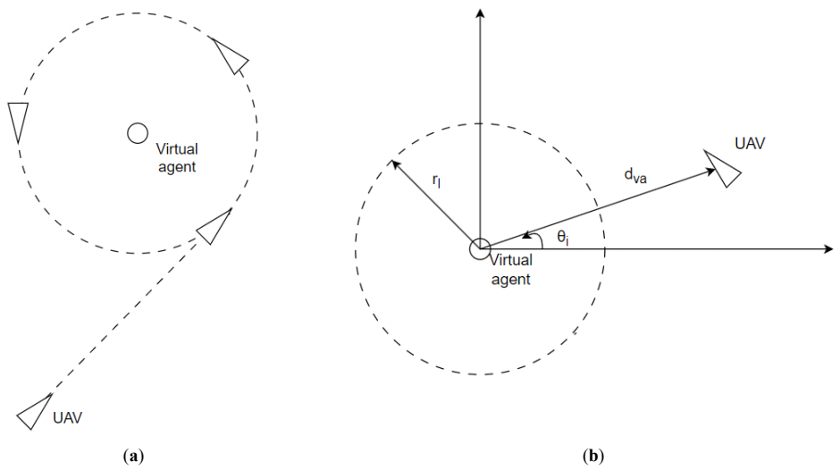
Figure 5. The virtual agent following. (<b>a</b>) The desired trajectory of the fixed wing UAV over a static virtual agent. (<b>b</b>) The relative position of the UAV towards the virtual agent, used for the calculation of desired yaw.
```latexthrust_{i}^{d}=0.7\times thrust_{max}+0.3\times s_{thrust}\big(d\vartheta_{av,i}\big),```
```latexs_{thrust}(x)=2\times(\frac{1}{1+e^{2.3\times x}}-0.5),```
```latexd\vartheta_{mn}=\vartheta_{m}-\theta_{n},```
6. Evaluation
The current section presents the experimental setup developed, the metrics used to evaluate the system’s performance, and the simulation results.
6.1. Experimental Setup
The proposed system has been implemented using the ROS framework [27], where each of the software modules fire map update, virtual agent placement, and UAV control were implemented as separate ROS nodes for each UAV of the system. A virtual and ideal fire detection & localization node was implemented to provide data on the cells covered by each UAV. The system was tested in Software In The Loop (SITL) simulations in the GAZEBO physics engine [28], using the PX4 autopilot [29] for low level control of the UAVs. The fixed wing UAV offered within the supported models of PX4, referred to as plane, was used as the vehicle’s platform.
For the experiments conducted in this work, each cell was 10 m × 10 m, while the area of interest was a square of 5 km × 5 km, generating a grid of 500 × 500 cells. The rest of the constants used for the conducted experiments are provided in Table 1.
Seven different experiment scenarios were designed to evaluate the proposed system. Each experiment ran in three repetitions with randomly generated fire of approximately the same size and evolved for 20 minutes, during which the fire was updated 190 times. The experiments were differentiated by the number of UAVs used, the initial and final fire size measured in the number of grid cells on fire, the fire spreading probability, and the activation or not of the collision avoidance and phase synchronization modules.
The seven experiments are summarized in Table 2. Experiments 1, 2, and 3 involve 4 UAVs. Experiment 1 assumes a relatively small fire size. Experiment 2 assumes a significantly larger fire size, spreading at the same rate. Experiment 3 assumes a medium range fire spreading at a higher rate. Experiments 2_1, and 3_1 are analog to experiments 2 and 3, however, they involve 8 UAVs. Finally, experiments 4 and 5 are based on experiment 2_1 with the collision avoidance, and the UAV synchronization respectively deactivated.
6.2. Metrics
Six metrics are defined and used to evaluate the system’s performance. The metrics are defined into three different categories as presented in Table 3. The measurements of each repetition of the experiments were averaged to compute the metric values for each experiment.
Three coverage metrics are proposed, namely the virtual agent coverage, the UAV coverage, and the UAV coverage efficiency. The coverage metrics are used to evaluate the capability of the system to provide optimal coverage in the area surrounding the fire, prioritizing the regions near the fire boundaries. The virtual agent coverage metric represents solely the behavior of the virtual agents, assuming that the UAVs perform a perfect orbit over their virtual agents. Therefore, the cells with distances smaller than the coverage radius rcov are assumed to be covered by the corresponding virtual agent. The metric is computed based on the monitoring area map described in Section 3.4. The union of the cells covered by virtual agents is computed and the priorities of the covered cells are summed. The metric is the average of the summed priorities of the covered cells over the summed priorities of all cells of the monitoring area. The UAV coverage metric is analogous to the virtual agent coverage to evaluate the actual coverage of the UAVs. The covered cells are counted over a period of time, set to 60 s for the experiments of this work. Finally, the UAV coverage efficiency metric indicates the instantaneous measured cell coverage performance of the system over the potential cell coverage performance. It is computed as the average of the percentage of the summed priorities of the union of the cells covered by the UAVs of the system over the total sum of the summed priorities of the cells covered by each UAV individually. It should be noted that the monitoring area map used for the computation of the coverage metrics is generated by the current and true fire state, not from the fire representation in the local fire map of the UAVs.
Two safety metrics are used to quantify the safety of the overall system. The number of UAV conflicts and the number of collisions metrics represent inter-vehicle safety issues. Similar metrics are proposed in [30]. Inter-UAV conflicts and collisions are counted as defined in Section 5.3.3.
Finally, the fire representation inaccuracy is introduced to evaluate the situational awareness of the system. It indicates the misrepresented cells on the local fire maps of the UAVs by comparing them to the true fire map. The misrepresented cells on each UAV are counted, and the metric is computed as the average number of cells flagged to the wrong state over the UAVs of the system.
6.3. Results
Figure 6 presents the trajectories of the four virtual agents during one of the repetitions of experiment 3. The left graph of the figure shows the initial deployment of the virtual agents, during the first 500 s of the experiment. The state of fire at the time is shown in red. The virtual agents settle in their positions. However, the fire is evolving, and they need to relocate during the rest of the experiment. The right graph of the figure shows the evolution of the fire and the response of the virtual agents. The fire state at time 500 s is shown in black, while the spread of the fire after that time is shown in red. The virtual agents move away from the fire as the fire size increases.
Figure 7 draws the trajectory of UAV 0 and its virtual agent. The UAV orbits its virtual agent using the virtual agent following method described. At the beginning of its trajectory, the virtual agent has a higher speed, while its speed decreases as it approaches the fire perimeter. Therefore, the loiter circles of the UAV present a larger displacement at the beginning of its trajectory (at the lower left of the figure) and converge into concentric circles at later stages of the trajectory when the virtual agent has settled into a static position.
6.3.1. Coverage
Figure 8 and Figure 9 present the virtual agent and the UAV coverage metrics respectively. Initially, the coverage is 0%, since the UAVs and their virtual agents are far away from the fire, outside of the virtual agent area. The UAV coverage presents the same behavior as the virtual agent coverage. The coverage for experiment 1 reaches 100%, demonstrating that 4 UAVs are capable of fully covering the small fire of that experiment. On the other hand, the coverage for experiments 2 and 3 does not surpass 67% and 83% respectively. Moreover, the coverage for experiment 3 shows a noticeable decrease with time, due to the high fire spreading probability. The 8 UAVs, used in experiments 2_1 and 3_1, are capable of fully covering the monitoring area in contrast to their 4 UAVs counterparts. Experiments 4 and 5 present no noticeable differences to experiment 2_1.
The UAV coverage efficiency is displayed in Figure 10. Initially, the coverage efficiency is 100% since no cells of the monitoring area are covered by the UAVs. The UAV coverage efficiency decreases for all experiments when the UAVs enter the monitoring area. The UAV coverage efficiency may be reduced by the non-optimal placement of virtual agents, or by the non-synchronized motion of the UAVs. It is observed that for all experiments except experiment 5, the coverage efficiency reaches 100%. The UAVs in experiment 5 did not apply the phase synchronization and therefore they do not create a formation with stable inter-vehicle distances.
6.3.2. Situational Awareness
Figure 11 presents the fire representation inaccuracy metric. The number of misrepresented cells increases at the beginning of the experiments, as the UAVs do not provide any coverage on the fire perimeter. Once the UAVs start covering the cells around the fire perimeter, the number of misrepresented cells rapidly decreases. Nevertheless, the inaccuracy raises for experiments 2 and 3. This is explained by the lack of complete coverage observed in the UAV coverage metric for those experiments. In the remaining experiments, in which the UAV coverage reaches a complete coverage near 100%, the fire representation inaccuracy is retained in very low numbers, demonstrating the performance of the system in monitoring the fire.
6.3.3. Safety
Figure 12 depicts the results of the two safety metrics. As expected, the number of conflicts for the experiments with 8 UAVs is significantly higher than the ones for the experiments with 4 UAVs. However, the percentage of conflicts leading to collisions remains approximately constant to 15% across all experiments except experiment 4. Experiment 4, in which the UAVs did not use the conflict resolution method to avoid a detected conflict, presented an increased percentage of conflicts that led to collisions, with 44% of the detected conflicts causing a collision. The number of collisions in experiment 4 is 3.6 times higher than the number of collisions in experiment 2_1, with which they share the same experiment setup.
Table 1. The selected constant values for the experiments.
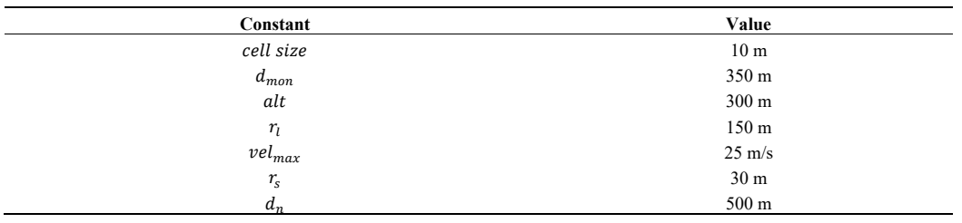
Table 2. The designed experiment scenarios.
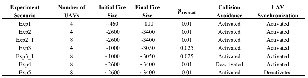
Table 3. The metrics used to evaluate the system’s performance.
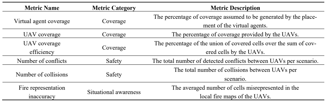
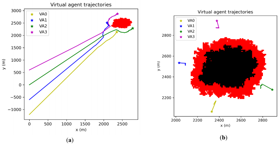
Figure 6. The trajectories of the virtual agents (VAs) for experiment 3. (<b>a</b>) The trajectories in the first 500 s of the experiment. (<b>b</b>) The trajectories for the time frame 500–1200 s.
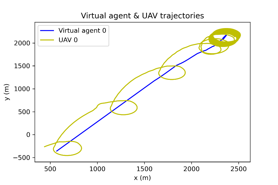
Figure 7. The trajectories of UAV 0 and its corresponding UAV for the first 500 s of experiment 3.
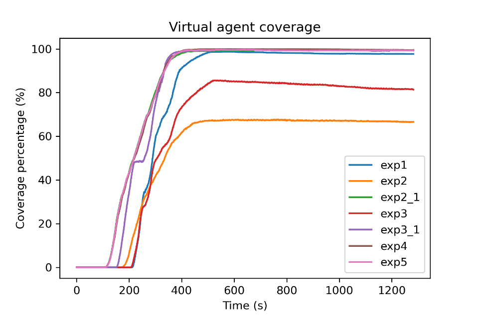
Figure 8. The virtual agent coverage over time for the seven experiments.
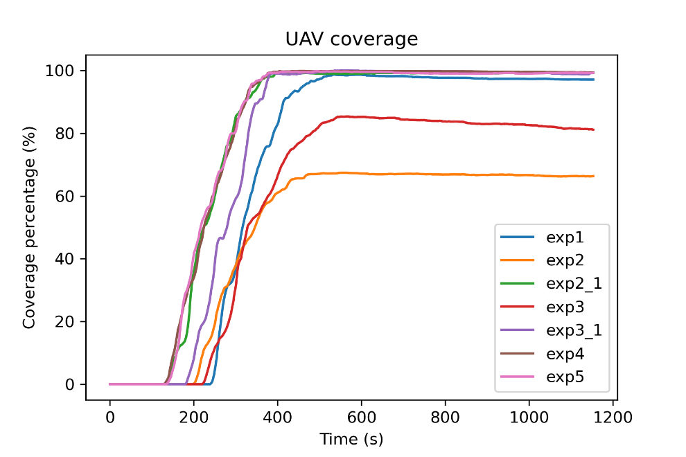
Figure 9. The UAV coverage over time for the seven experiments.
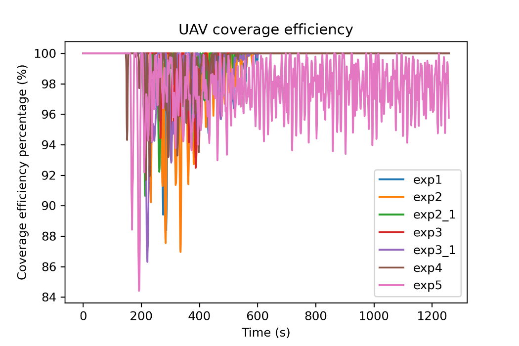
Figure 10. The UAV coverage efficiency over time for the seven experiments.
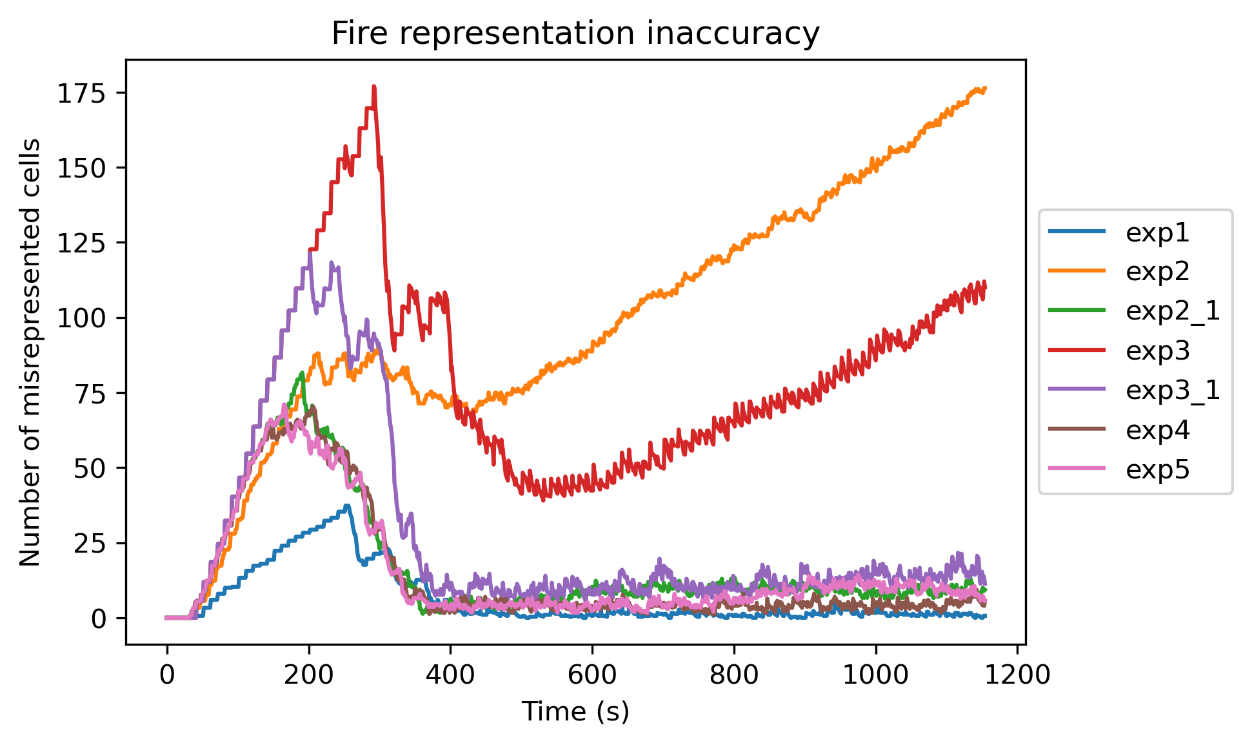
Figure 11. The fire representation accuracy over time for the seven experiments.
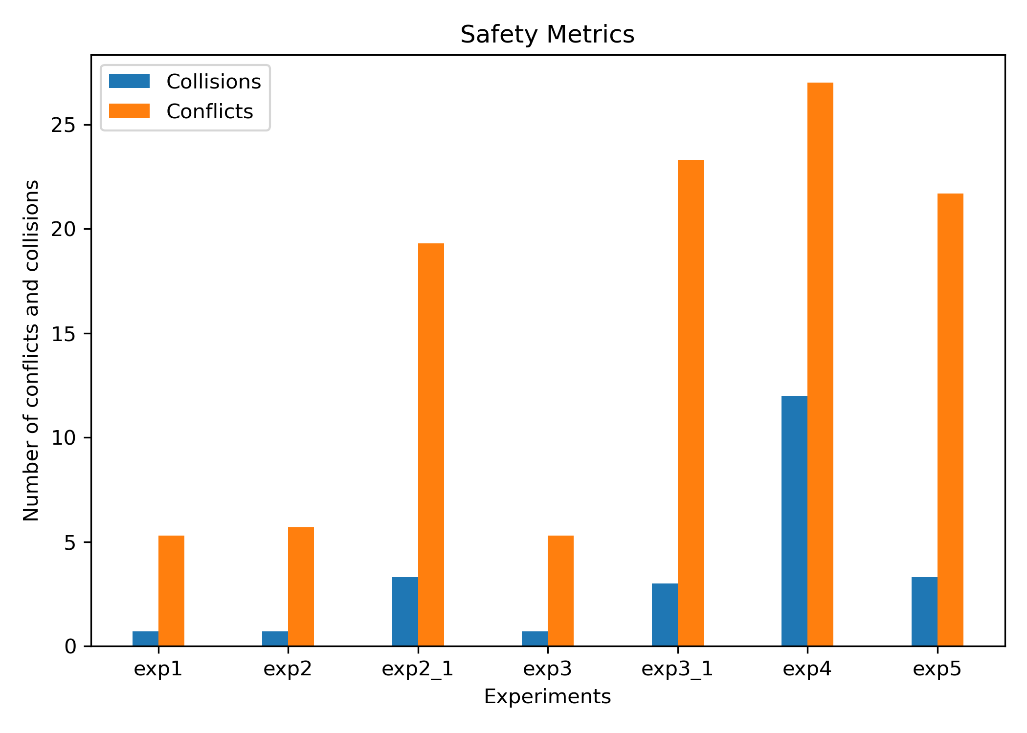
Figure 12. The safety metrics for the seven experiments.
7. Discussion
The simulation results of the system provide some interesting insights into the performance of the system. Experiment 4, in which the collision avoidance component was deactivated, showed an increase in the number of collisions, and a triplication in the percentage of conflicts that concluded into collisions in comparison to the rest of the experiments. This result underlines the importance of the collision avoidance module in the system. Nevertheless, the used collision avoidance methodology did not eliminate inter-vehicle collisions. Moreover, as shown by experiment 4, in which detected conflicts were not eliminated, over half (56%) of the detected conflicts did not lead to a collision. The used collision avoidance takes as input the position and intended velocity of the UAV and the more recent known position and velocity of the neighboring UAV. Therefore, the intention of the other UAV is not known and is not considered in the conflict detection or resolution. As the UAVs constantly orbit over their virtual agents, their heading changes rapidly, and intended velocity differentiates from the current. Hence, it would be appropriate to integrate a collision avoidance method that considers the intention of other UAVs. This could reduce the detected conflicts which do not eventually lead to a collision.
Another point for consideration is the fire map synchronization. During experiments, the fire representation inaccuracy was observed to have very similar values across all UAVs of the system. In the performed experiments communications were assumed to be nominal and no packet loss was observed. However, in real-world scenarios, some fire update messages may be lost. The proposed fire map update logic is not equipped to deal with such uncertainties. Therefore, this would result in accumulative errors. Depending on the frequency of the communication failures, this may not result in a significant decrease in the coverage performance of the system, since each UAV would still maintain an accurate representation of its region. However, such uncertainties and their effect should be tested, and a fire map synchronization logic may need to be implemented to synchronize the representation on each UAV by transmitting the whole fire map periodically.
Finally, it should be noted that while this system is designed for wildfire monitoring, this work does not investigate the utilization of the collected information. The ultimate purpose of the system is to collect data on the fire and generate an updated situational awareness picture. Therefore, the system contributes to the firefighting and fire management operations by providing updated situational awareness data, which is required for effective fire management [31]. The results of the Fire Representation Inaccuracy metric indicate that the proposed system manages to produce an updated and correct situational awareness picture of the current state of the fire, mapping its spread. The collected data can be used by a human user or a Decision Support System (DSS) in order to generate informed decisions on how to contain or extinguish the fire. Although it is outside of the scope of the work at hand, the human-machine interaction is a highly important aspect of the future system.
8. Conclusions
This paper proposes and studies a multi-UAV system with fixed wing planes, designed to persistently monitor the perimeter of an active wildfire. The methods are designed to work in a decentralized and scalable manner. Methods are described for the local fire representation on each agent and the update logic, for the virtual agent formation, and for the UAV control to guide the UAVs to efficiently and safely follow the virtual agents and create a synchronized formation. The system was tested in SITL simulations for seven different scenarios with four or eight UAVs, and the proposed system was evaluated on six metrics.
The results of experiments 1–3_1 demonstrate the efficiency of the system in covering the area of interest and maintaining an updated representation of the fire. The virtual agent and UAV coverage reached near 100% values for experiments 1, 2_1, 3_1, and the fire representation inaccuracy remained very low throughout the experiment. The number of UAVs proved to be insufficient for experiments 2 and 3, as the four UAVs were not able to completely cover the larger fire sizes of those experiments. Experiments 4 and 5 show the importance of collision avoidance and UAV synchronization respectively. The comparison of experiment 4 to the rest of the experiments in regards to the safety metrics exhibits the positive effect of the collision avoidance component on the safety of the UAVs, as it significantly reduces inter-vehicle collisions. Furthermore, the results of experiment 5 on the UAV coverage efficiency metric report on the effectiveness of the UAV synchronization methodology and its importance.
Future research should conduct more extensive scalability testing and proceed into real-world experiments. The experiments conducted for this work were limited to systems with up to eight UAVs due to processing power limitations. Further testing is required to validate the system’s performance and convergence with larger numbers of UAVs. Moreover, the proposed system was tested in SITL simulations for the purposes of this work. Real-world testing is expected to provide more insights into communication issues (e.g., temporal loss of communications) and sensor processing uncertainties (e.g., low confidence in fire detection or low fire localization accuracy), which shall guide the system’s further development.
Author Contributions
Ethics Statement
Not applicable.
Informed Consent Statement
Funding
This research received no external funding.
Declaration of Competing Interest
The authors declare that they have no known competing financial interests or personal relationships that could have appeared to influence the work reported in this paper.
References
1.
Merino L, Caballero F, Martínez-de-Dios JR, Maza I, Ollero A. Automatic Forest Fire Monitoring and Measurement using Unmanned Aerial Vehicles. In Proceedings of the VI International Conference on Forest Fire Research, Coimbra, Portugal, 15–18 November 2010.
2.
Casbeer DW, Kingston DB, Beard RW, McLain TW. Cooperative Forest Fire Surveillance Using a Team of Small Unmanned Air Vehicles. Int. J. Syst. Sci. 2006, 37, 351–360. doi:10.1080/00207720500438480. [Google Scholar]
3.
Akhloufi M, Couturier A, Castro N. Unmanned Aerial Vehicles for Wildland Fires: Sensing, Perception, Cooperation and Assistance. Drones 2021, 5, 15. doi:10.3390/drones5010015. [Google Scholar]
4.
Yu Z, Zhang Y, Jiang B, Yu X. Fault-Tolerant Time-Varying Elliptical Formation Control of Multiple Fixed-Wing UAVs for Cooperative Forest Fire Monitoring. J. Intell. Robot. Syst. 2021, 101, 48. doi:10.1007/s10846-021-01320-6. [Google Scholar]
5.
Bailon-Ruiz R, Lacroix S. Wildfire remote sensing with UAVs: A review from the autonomy point of view. In Proceedings of the 2020 International Conference on Unmanned Aircraft Systems (ICUAS), Athens, Greece, 1–4 September 2020, doi:10.1109/ICUAS48674.2020.9213986.
6.
Hu J, Niu H, Carrasco J, Lennox B, Arvin F. Fault-tolerant cooperative navigation of networked UAV swarms for forest fire monitoring. Aerosp. Sci. Technol. 2022, 123, 107494. doi:10.1016/j.ast.2022.107494. [Google Scholar]
7.
Bailon-Ruiz R, Bit-Monnot A, Lacroix S. Real-time wildfire monitoring with a fleet of UAVs. Robot. Auton. Syst. 2022, 152, 104071. doi:10.1016/j.robot.2022.104071. [Google Scholar]
8.
Martínez-de-Dios J, Merino L, Ollero A, Ribeiro L, Viegas X. Multi-UAV Experiments: Application to Forest Fires. In Multiple Heterogeneous Unmanned Aerial Vehicles; Ollero A, Mazza I, Eds.; Springer: Berlin/Heidelberg, Germany, 2007; Volume 37, pp. 207–228, doi:10.1007/978-3-540-73958-6_8.
9.
Shrestha K, Dubey R, Singandhupe A, Louis S, La H. Multi Objective UAV Network Deployment for Dynamic Fire Coverage. In Proceedings of the 2021 IEEE Congress on Evolutionary Computation (CEC), Kraków, Poland, 28 June–1 July 2021, doi:10.1109/CEC45853.2021.9504947.
10.
Pham HX, La HM, Feil-Seifer D, Deans M. A distributed control framework for a team of unmanned aerial vehicles for dynamic wildfire tracking. In Proceedings of the 2017 IEEE/RSJ International Conference on Intelligent Robots and Systems (IROS), Vancouver, BC, Canada, 24–28 September 2017, doi:10.1109/IROS.2017.8206579.
11.
Kumar M, Cohen K, HomChaudhuri B. Cooperative Control of Multiple Uninhabited Aerial Vehicles for Monitoring and Fighting Wildfires. J. Aerosp. Comput. Inf. Commun. 2011, 8, 1–16. doi:10.2514/1.48403. [Google Scholar]
12.
Saffre F, Hildmann H, Karvonen H, Lind T. Monitoring and Cordoning Wildfires with an Autonomous Swarm of Unmanned Aerial Vehicles. Drones 2022, 6, 301. doi:10.3390/drones6100301.[Google Scholar]
13.
Ghamry KA, Zhang Y. Cooperative control of multiple UAVs for forest fire monitoring and detection. In Proceedings of the 2016 12th IEEE/ASME International Conference on Mechatronic and Embedded Systems and Applications (MESA), Auckland, New Zealand, 29–31 August 2016, doi:10.1109/MESA.2016.7587184.
14.
Afghah F, Razi A, Chakareski J, Ashdown J. Wildfire Monitoring in Remote Areas using Autonomous Unmanned Aerial Vehicles. In Proceedings of the IEEE INFOCOM 2019—IEEE Conference on Computer Communications Workshops (INFOCOM WKSHPS), Paris, France, 29 April–2 May 2019, doi:10.1109/INFCOMW.2019.8845309.
15.
Kinaneva D, Hristov G, Raychev J, Zahariev P. Early Forest Fire Detection Using Drones and Artificial Intelligence. In Proceedings of the 2019 42nd International Convention on Information and Communication Technology, Electronics and Microelectronics (MIPRO), Opatija, Croatia, 20–24 May 2019, doi:10.23919/MIPRO.2019.8756696.
16.
Yuan C, Liu Z, Zhang Y. UAV-based Forest Fire Detection and Tracking Using Image Processing Techniques. In Proceedings of the 2015 International Conference on Unmanned Aircraft Systems (ICUAS), Denver, CO, USA, 9–12 June 2015, doi:10.1109/ICUAS.2015.7152345.
17.
Yuan C, Liu Z, Zhang Y. Vision-based Forest Fire Detection in Aerial Images for Firefighting Using UAVs. In Proceedings of the 2016 International Conference on Unmanned Aircraft Systems (ICUAS), Arlington, VA, USA, 7–10 June 2016, doi:10.1109/ICUAS.2016.7502546.
18.
Chen X, Hopkins B, Wang H, O’Neill L, Afghah F, Razi A, et al. Wildland Fire Detection and Monitoring Using a Drone-Collected RGB/IR Image Dataset. IEEE Access 2022, 10, 121301–121317. doi:10.1109/ACCESS.2022.3222805. [Google Scholar]
19.
Sherstjuk V, Zharikova M, Sokol I. Forest Fire-Fighting Monitoring System Based on UAV Team and Remote Sensing. In Proceedings of the 2018 IEEE 38th International Conference on Electronics and Nanotechnology (ELNANO), Kyiv, Ukraine, 24–26 April 2018, doi:10.1109/ELNANO.2018.8477527.
20.
Giuseppi A, Germanà R, Fiorini F, Priscoli FD, Pietrabissa A. UAV Patrolling for Wildfire Monitoring by a Dynamic Voronoi Tessellation on Satellite Data. Drones 2021, 5, 130. doi:10.3390/drones5040130. [Google Scholar]
21.
Alexandridis A, Vakalis D, Siettos C, Bafas G. A cellular automata model for forest fire spread prediction: The case of the wildfire that swept through Spetses Island in 1990. Appl. Math. Comput. 2008, 204, 191–201. doi:10.1016/j.amc.2008.06.046. [Google Scholar]
22.
Zhao H, Wei J, Huang S, Zhou L, Tang Q. Regular Topology Formation Based on Artificial Forces for Distributed Mobile Robotic Networks. IEEE Trans. Mob. Comput. 2018, 18, 2415–2429. doi:10.1109/TMC.2018.2873015. [Google Scholar]
23.
Dubey R, Louis SJ, Sengupta S. Evolving Dynamically Reconfiguring UAV-hosted Mesh Networks. In Proceedings of the 2020 IEEE Congress on Evolutionary Computation (CEC), Glasgow, UK, 19–24 July 2020, doi:10.1109/CEC48606.2020.9185639.
24.
Zhu S, Wang D, Low CB. Ground Target Tracking Using UAV with Input Constraints. J. Intell. Robot. Syst. 2013, 69, 417–429. doi:10.1007/s10846-012-9737-y. [Google Scholar]
25.
Varga M, Basiri M, Heitz G, Floreano D. Distributed Formation Control of Fixed Wing Micro Aerial Vehicles for Area Coverage. In Proceedings of the 2015 IEEE/RSJ International Conference on Intelligent Robots and Systems (IROS), Hamburg, Germany, 28 September–2 October 2015, doi:10.1109/IROS.2015.7353444.
26.
van den Berg J, Lin M, Manocha D. Reciprocal Velocity Obstacles for Real-Time Multi-Agent Navigation. In Proceedings of the 2008 IEEE International Conference on Robotics and Automation, Pasadena, CA, USA, 19–23 May 2008, doi:10.1109/ROBOT.2008.4543489.
27.
Quigley M, Conley K, Gerkey B, Faust J, Foote T, Leibs J, et al. ROS: An open-source Robot Operating System. In Proceedings of the ICRA Workshop on Open Source Software, Kobe, Japan, 12–17 May 2009.
28.
Koenig N, Howard A. Design and Use Paradigms for Gazebo, An Open-Source Multi-Robot Simulator. In Proceedings of the 2004 International Conference on Intelligent Robots and Systems, Sendai, Japan, 28 September–2 October 2004, doi:10.1109/IROS.2004.1389727.
29.
Meier L, Honegger D, Pollefeys M. PX4: A Node-Based Multithreaded Open Source Robotics Framework. In Proceedings of the 2015 IEEE International Conference on Robotics and Automation (ICRA), Seattle, WA, USA, 26–30 May 2015, doi:10.1109/ICRA.2015.7140074.
30.
Bulusu V, Polishchuk V, Sengupta R, Sedov L. Capacity Estimation for Low Altitude Airspace. In Proceedings of the 17th AIAA Aviation Technology, Integration, and Operations Conference, Denver, Colorado, 5–9 June 2017, doi:10.2514/6.2017-4266.
31.
Zambrano M, Esteve M, Pérez I, Carvajal F, Zambrano A. Situation awareness in the large forest fires response. A solution based on wireless mesh networks. In Proceedings of the 2017 IEEE 9th Latin-American Conference on Communications (LATINCOM), Guatemala City, Guatemala, 8–10 November 2017, doi:10.1109/LATINCOM.2017.8240147.