1. Introduction
Elastomers, known for their versatility and wide-ranging applications across various industries, hold a vital position in the realm of science and technology. Their exceptional elasticity and elongation at break make them significant for numerous applications. To further enhance their existing properties and introduce new functionalities such as electrical and thermal conductivity, elastomers are compounded with nanomaterials, giving rise to elastomer nanocomposites [
1,
2]. In the context of nanocomposite preparation, latex compounding offers several environmental and operational advantages, as the fillers are added and coagulated prior to milling. This method reduces milling time, in alignment with growing environmental and safety concerns in manufacturing [
3].
Among various filler materials, carbon-based nanomaterials have garnered attention for their potential to enhance the mechanical and functional properties of polymers. These materials primarily comprise carbon atoms arranged in several nanostructures; in comparison with those fillers based on metals or metal oxides, carbon nanomaterials are more compatible with polymers, particularly graphene nanoplatelets [
4,
5,
6] and carbon nanotubes (CNTs) [
7,
8]. While carbon black has been traditionally used as a reinforcing filler in elastomers due to its ability to enhance mechanical properties like tensile strength and abrasion resistance, CNTs offer a more advanced level of reinforcement. Their high aspect ratio and tubular structure form a more continuous and efficient network within the elastomer matrix, not only improving mechanical strength but also adding functionalities such as electrical conductivity and thermal stability that carbon black cannot provide. CNTs are composed of rolled-up graphene sheets and exist in either single-walled (SWCNTs) with one graphene layer or multi-walled (MWCNTs) with several concentric graphene layers. These nanotubes possess exceptional mechanical, thermal and electrical properties, and they are highly effective in improving elastomer performance for applications such as electromagnetic interference shielding and strain sensing [
9,
10,
11].
However, a grand challenge is to achieve uniform dispersion and strong interfacial interaction of CNTs within an elastomer matrix. If not addressed, it often results in poor mechanical and electrical properties of the composites. Vazquez-Martinez et al. reported that dispersed SWCNTs in an elastomer matrix led to improved cross-linking and mechanical properties [
12]. However, it is noteworthy that their method involved the use of xylene as a solvent, which poses significant health and environmental risk. This highlights the importance of exploring safer alternatives for dispersing CNTs in elastomer matrices.
Surface modification of CNTs has been explored to enhance their compatibility with and dispersion within the matrix. The use of non-reactive surfactants for the surface modification of nanoparticles [
13,
14] offers several benefits, notably preserving the structural integrity of nanofillers, thereby retaining their electrical and mechanical properties [
15,
16].
In this context, the use of surfactants such as polyethylene glycol tert-octylphenyl ether (Triton X-100) has shown promise. A comparative study of CNT dispersion by Rastogi et al. [
17] revealed that Triton X-100 would provide maximum dispersion among the surfactants tested,
i.e., Triton X-100, Tween 20, Tween 80 and sodium dodecyl sulfate (SDS). The presence of the benzene rings in the tail of Triton X-100 molecules enhances its ability to adsorb onto the nanotube surface through π–π interactions, leading to a more effective dispersion of CNTs in the aqueous solution. This improved dispersion is expected to promote the interactions of CNTs with the polymer matrix, thereby enhancing the overall properties of the nanocomposites. Srivastava et al. reported that the incorporation of MWCNTs in elastomers yielded significant improvements in mechanical properties [
18]. Bokobza conducted a comparative analysis of the electrical and mechanical characteristics of two groups of elastomer composites, respectively containing MWCNTs and carbon black. The study observed that MWCNT nanocomposites exhibited superior properties compared to those with carbon black [
19].
Understanding the influence of different factors, especially the dimension, structure and dispersion of nanoparticles, is essential for optimizing the design and performance of polymer nanocomposites. A comparative study of elastomer nanocomposites containing SWCNTs and MWCNTs is therefore crucial. It enables an in-depth examination of how the dimension, structure and dispersion of nanoparticles influence the properties of the resulting nanocomposites.
The first hypothesis of this study posits that elastomer nanocomposites containing SWCNTs may exhibit enhanced electrical conductivity compared to those filled with MWCNTs, owing to the superior electrical conductivity of SWCNTs.
The second hypothesis suggests that elastomer nanocomposites containing SWCNTs would display superior tensile strength and elongation at break. This is expected due to the impressive tensile strength of SWCNTs, which ranges 50–100 GPa and their flexibility and thinner diameter, which allows for more tubes at a given fraction of composites than MWCNTs.
The third hypothesis focuses on the dispersion and interaction of SWCNTs and MWCNTs within the elastomer matrix, proposing that these factors will significantly influence the mechanical and electrical properties of the nanocomposites. Improved dispersion and better interfacial interaction are expected to lead to overall high performance.
This study aims to fill these research gaps and to advance the body of knowledge surrounding elastomer/CNT nanocomposites, by providing a detailed comparative investigation on the mechanical and electrical properties of two groups of elastomer nanocomposites respectively containing SWCNTs or MWCNTs.
2. Experimental Procedure
2.1. Materials
Purified MWCNTs (model number BT1001M, diameter 10–20 nm and purity >94%) were obtained from LG Chem Co., Ltd. in Seoul, South Korea, and SWCNTs (mean diameter 1.8 ± 0.4 nm and length ~5nm) were purchased from Techinstro, Yadav Nagar, Nagpur-Maharashtra in India. Nitrile butadiene rubber in a latex form (NBR, 630N, 42–43% solid) was procured from NANTEX Industry Co., Ltd., Lin-Yuan, Kaohsiung in Taiwan. Polyethylene glycol tert-octylphenyl ether (Triton X-100), Sulfur, Dicumyl peroxide (DCP) and N,N-m-phenylenedimaleimide (HVA-2) were purchased from Sigma-Aldrich in Melbourne, Australia.
Different treatments were applied to SWCNTs and MWCNTs due to the varying purity levels of the starting materials. SWCNTs were subjected to a purification process to remove impurities and enhance their quality. In contrast, MWCNTs were used as received without further purification, as they were already in a purified state. The decision to purify only SWCNTs was based on the initial assessment of the material quality, which indicated the presence of impurities in the SWCNTs that could potentially affect the properties of the resulting nanocomposites.
2.2. Methods
2.2.1. Purification of SWCNTs and Surface Modification of CNTs
To purify the SWCNTs, a reflux process was employed by using 250 mg of SWCNTs in a 200 mL of nitric acid (2 M). Nitric acid (HNO
3) was used to remove amorphous carbon and other carbonaceous impurities. The refluxing procedure was carried out for a duration of 4 h, with the solution being changed halfway through, specifically after 2 h. Once the refluxing was completed, the resulting material underwent filtration and was rinsed with deionised water until reaching a neutral pH. Subsequently, the material was transferred to a beaker containing 100 mL of 0.2 M hydrochloric acid (HCl), which was used to remove any residual metal catalysts. The mixture was stirred for 30 min, followed by more filtration and subsequent washing with deionised water until a neutral pH was achieved. The material was then dried overnight in a fanned oven at 60 °C.
The modification of MWCNTs commenced by dissolving polyethylene glycol tert-octylphenyl ether (Triton X-100) in water to form a solution at 1 wt.%. Subsequently, 1 g of MWCNTs were added to the solution, followed by stirring at 250 rpm for 15 min. The resulting mixture underwent sonication below room temperature for 45 min. It is worth noting that sonication in an ice bath has been reported to be an effective method for dispersing nanomaterial suspensions [
20,
21]. After the sonication process, the mixture was washed with deionised water, followed by filtration and vacuum-drying overnight at 60 °C to obtain modified MWCNTs. The same procedure was applied to the purified SWCNTs for surface modification. The dried CNTs were used for TGA and Raman characterisation, whereas a dispersion of CNTs was used for latex compounding.
2.2.2. Preparation of Nanocomposites
CNTs were sonicated for 60 min and mixed with the NBR latex using magnetic stirring at 360 rpm for 30 min. Filler fractions are detailed in Section S2 of the Supporting Information. To initiate coagulation, 1 wt./vol.% CaCl
2 solution was added to the CNT/latex mixture in a 1:1 volume ratio. The resulting coagula were subsequently washed with deionized water to eliminate any residual CaCl
2. Afterwards, the coagula were dried overnight in a ventilated oven at 60 °C. The sample was then subjected to two-roll milling, during which 5 rolls and 5 triangles were made. Predetermined quantities of vulcanisation agents (as specified in ) were incorporated during the process. The vulcanization process took place at 150 °C under 10 MPa for 30 min. These specific conditions were determined based on recipe optimization by using an oscillating disk rheometer (ZWL-III Rheometer, Yangzhou, China).
. Vulcanization recipes.
| Material |
Weight (g) |
| NBR |
100 |
| Sulfur |
1 |
| N,N′-m-phenylenedimaleimide (HVA-2) |
1 |
| Dicumyl peroxide (DCP) |
4 |
| MWCNTs or SWCNTs |
Variable |
2.2.3. Characterisation and Testing of Nanocomposite Properties
The thermal degradation characteristics of both pristine and purified CNTs were investigated using a Discovery TGA (TA Instruments in Adelaide, Australia). The experiment was conducted in an oxygen-purged chamber, with a controlled ramping rate of 10 °C/min, reaching a maximum temperature of 900 °C. The Raman spectra of the SWCNTs were ascertained using a LabRAM HR Evol Raman spectrometer. The scan range was 500–2000 cm
−1 with a laser wavelength of 633 nm.
The morphology of both pristine and purified SWCNTs was analysed using a scanning electron microscope (Zeiss Merlin FEG SEM in Adelaide, Australia) at 2 kV. Additionally, the microstructures of the nanocomposites prepared from the brittle-fractured samples, which were pre-immersed in liquid N
2 and surface coated, were characterised using the same instrument. For further clarity and detailed information, the pristine and purified SWCNTs and cryo-microtomed samples of the nanocomposites were examined using transmission electron microscopy (Tecnai G2 Spirit, EDAX TEAM EDS wSDD Detector in Adelaide, Australia) at 80 kV.
Thin films with a diameter of 40 mm and an average thickness of 18 μm for pristine MWCNTs and 8 μm for purified SWCNTs were prepared by adding 5 mg of each type of CNTs to ethanol and sonicating for 30 min. The resulting mixture was then filtered. The product on the filter paper was covered with a plain polymer substrate and two circular metallic pieces. The filter paper and substrate were placed in between the metallic pieces, and hydraulically pressed at 5 MPa for 7 times. The product, which was then transferred to the polymer substrate, was dried for 2 h at room temperature (see schematic in Section S1 of supporting information). Their electrical conductivity was assessed using a 4-probe system source meter (Keithley 2602B in Adelaide, Australia). The electrical conductivity of the nanocomposites, with a diameter of 50 mm and a thickness of 1 mm, was measured utilizing a 2-probe Agilent 4339B high resistance meter (6000B cell) in Adelaide, Australia at a voltage of 0.1 V.
The mechanical properties of dumbbell die-cut samples (gauge section 20 × 4 × 1 mm
3) were evaluated using an Instron 5567, equipped with a 2 kN load cell. The tests were conducted at a crosshead speed of 100 mm/min. The reported results reflect the average values of at least three samples obtained from the stress-strain graphs generated during testing. All mechanical tests were carried out in accordance with ASTM D638-02a, the standard test method for tensile properties of plastics.
A swelling experiment was conducted by immersing all samples (dimension 10 × 3 × 1 mm) in toluene, an organic solvent, until they reached equilibrium swelling over 24 h. Subsequently, the swelling ratio and crosslink densities were estimated for each sample using Equations (1)–(3).
where
χ represents the Flory/Huggins interaction parameter (0.435) between toluene and NBR [
22],
Vs denotes the molar volume of toluene (106.3 cm
3/mol) and
Vr signifies the volume fraction of NBR. The volume fraction of NBR can be determined using Equation (2).
The parameters
W1 and
W2 correspond to the initial and final weights of the nanocomposite. The density ratio of NBR to toluene, known to be 1.12, is represented as η in the equation. Also, the swelling ratio (
ζ) of each nanocomposite can be estimated using Equation (3).
3. Results and Discussion
3.1. Purification of SWCNTs
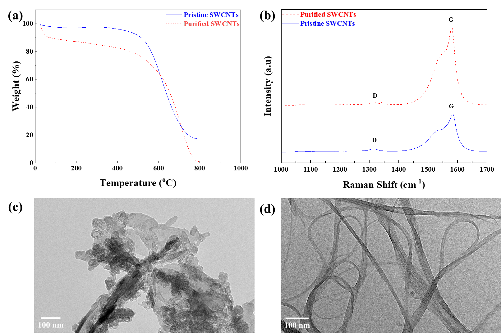
a illustrates the thermogravimetric analysis (TGA) of both pristine and purified SWCNTs. The TGA graph of pristine SWCNTs exhibits a subtle weight increase at approximately 350 °C, which can be attributed to the presence of amorphous carbon and the oxidation of the metal catalyst in the sample [
23]. The thermal stability is centred around 550 °C, and ~20 wt.% of the remaining mass at 800 °C is ascribed to the residual metal catalyst.
For the purified SWCNTs, the initial weight loss in the low-temperature range can be attributed to the removal of volatile and less stable components. In contrast to pristine SWCNTs, the absence of a subtle mass increase on the purified SWCNTs graph at 350 °C suggests that the purification process was effective. Moreover, the thermal stability of SWCNTs extends to about 600 °C, indicating the successful removal of the metal catalyst and decomposition of amorphous carbon due to the acid treatment. The elimination of the metal catalyst is considered to enhance the activation energy during the oxidation of SWCNTs, thereby increasing their overall stability. The purification process seems to have enhanced the overall stability of SWCNTs by possibly removing other components that were more susceptible to decomposition or oxidation at lower temperatures.
In b, the Raman spectra of both pristine and purified SWCNTs are presented. Two prominent peaks are observed: one at ~1320 cm
−1 corresponding to structural defects arising from disordered sp2 carbon (D-band) [
24] and another at ~1590 cm
−1, representing the in-plane vibration of the sp2 bonded structure (G-band) [
21]. The ratio of the areas under the D and G bands (ID/IG) was calculated to be 0.183 and 0.141 for pristine and purified SWCNTs, respectively. This ratio serves as an estimate of the degree of defects present in the SWCNTs. The lower ID/IG for the purified SWCNTs suggests an improvement in the SWCNT content [
24].
To comprehensively understand the purification process, Transmission Electron Microscopy (TEM) images were obtained. c depicts bundles of SWCNTs that appear to be coated with impurities, likely consisting of both carbonaceous and metal impurities [
24,
25]. However, through the treatment with nitric acid, these impurities were eliminated (d). Treatment with HNO
3 dissolves the metal catalyst, forming metal nitrates. This process significantly reduces the metal impurities. Subsequent washing with HCl after nitric acid treatment yields metal chlorides. These chlorides, along with excess metal impurities, are soluble in water and can be easily removed during the rinsing process. Additionally, HCl serves an additional purpose as an etchant for carbonaceous impurities [
26,
27].
. (<b>a</b>) TGA graphs of pristine and purified SWCNTs. (<b>b</b>) Raman spectra of pristine and purified SWCNTs, showing the D-band (~1320 cm<sup>−1</sup>) associated with structural defects and the G-band (~1590 cm<sup>−1</sup>) representing the in-plane vibration of sp2-bonded carbon. TEM images of pristine (<b>c</b>) and purified (<b>d</b>) SWCNTs.
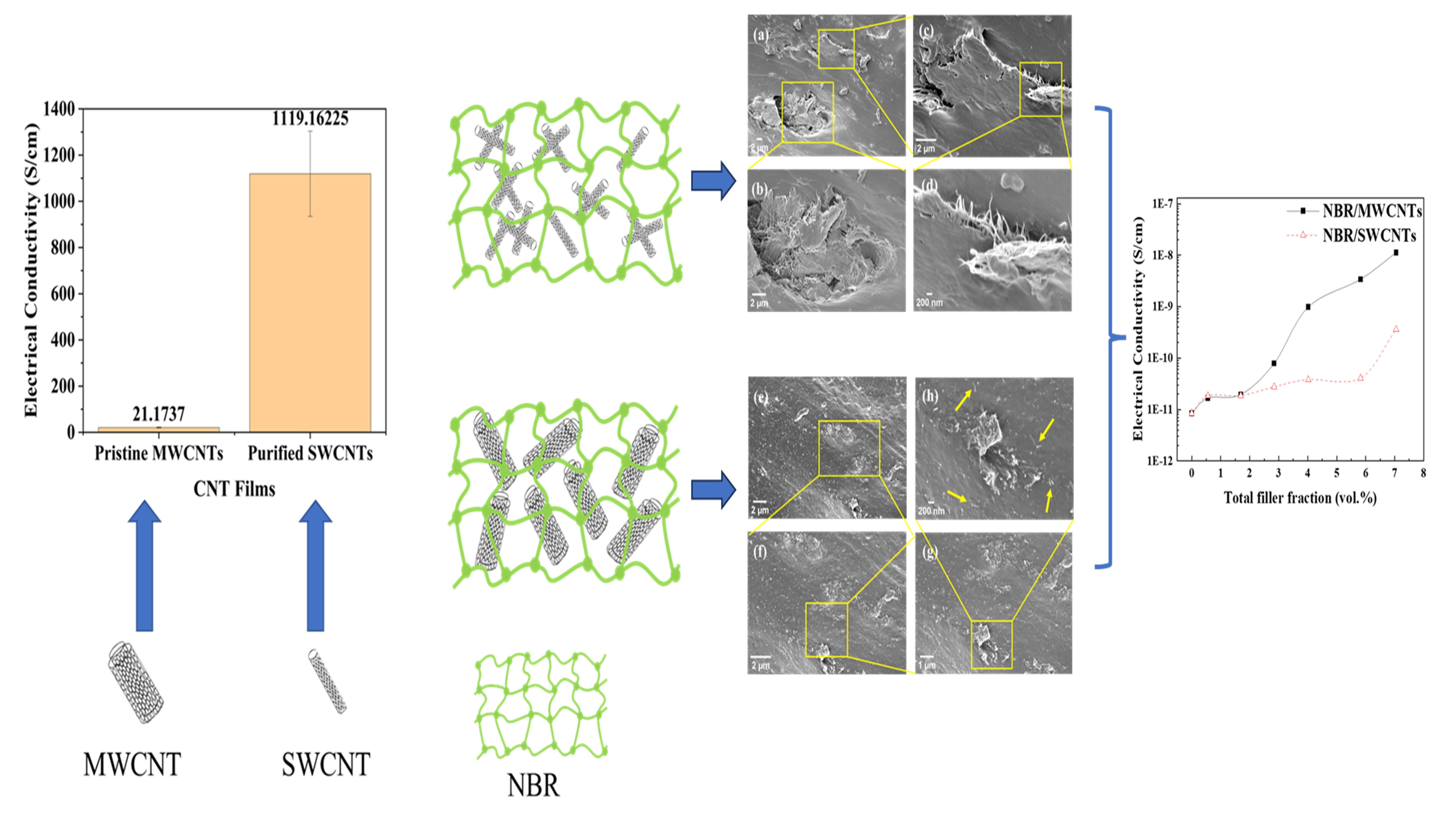
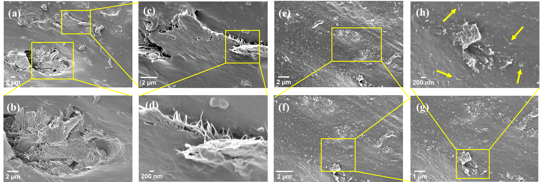
Surface modification of both SWCNTs and MWCNTs by polyethylene glycol tert-octylphenyl ether (Triton X-100) was performed prior to compounding with latex NBR. This preparatory step was intended to promote better integration between the fillers and the matrix. Nevertheless, SWCNTs (a–d) are prone to form substantial agglomerates in the elastomer matrix, likely due to their intrinsic high aspect ratio and the strong van der Waals attractions. By contrast, MWCNTs (e–h) display a relatively better dispersion in the elastomer matrix, characterized by smaller and less clustered agglomerates. The diminished agglomerate size points to an increased interfacial area which could lead to improved load transfer and electrical conductivity due to a more efficient CNT network. The dispersion of individual MWCNTs (indicated with yellow arrows in h) is pivotal for the nanocomposite, as it directly correlates with elevated tensile strength and electrical conductivity.
. SEM micrographs of (<b>a</b>–<b>d</b>) NBR/SWCNT nanocomposite and (<b>e</b>–<b>h</b>) NBR/MWCNT nanocomposite, both at 7.05 vol.%.
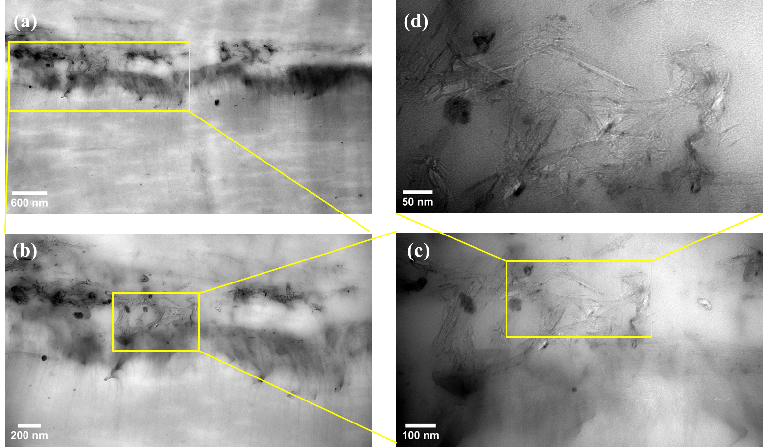
To further investigate the dispersion of CNTs within the NBR matrix, Transmission Electron Microscopy (TEM) was employed to analyse the two groups of nanocomposites. TEM micrographs of the SWCNT nanocomposite reveal distinct regions, with a,b showing significant agglomerations within the NBR matrix, consistent with the SEM analysis in a–d. At higher magnifications (c,d), SWCNTs appear disentangled but still clustered. The small diameter of SWCNTs, typically around 1–2 nm, contributes to their tendency to form clusters due to their high surface area-to-volume ratio, which increases van der Waals forces between individual tubes [
28,
29,
30].
. TEM micrographs of NBR/SWCNT nanocomposite at 7.05 vol.%, showing significant agglomerations within the NBR matrix (<b>a</b>,<b>b</b>). At higher magnifications (<b>c</b>,<b>d</b>), SWCNTs appear disentangled but remain clustered due to their small diameter (1–2 nm) and high surface area-to-volume ratio, which increases van der Waals forces.
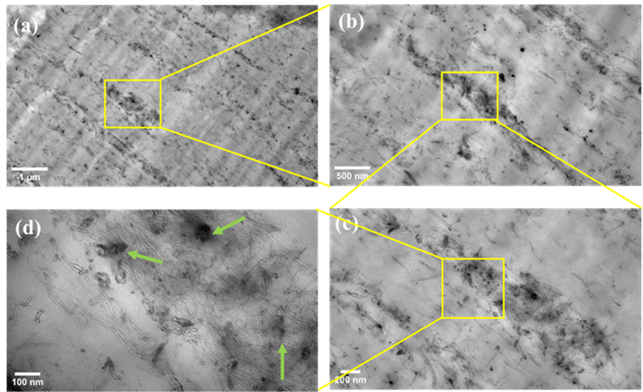
The NBR/MWCNT nanocomposite depicted in a–d shows a markedly different morphology. The micrographs reveal a relatively uniform dispersion of MWCNTs within the NBR matrix, characterized by fewer and smaller agglomerates, as indicated by green arrows in d. The disparity in dispersion between SWCNTs and MWCNTs is attributed to their intrinsic differences in dimension and flexibility. The larger diameter of MWCNTs, typically around 10–20 nm, reduces the surface area-to-volume ratio, thereby decreasing van der Waals forces and facilitating better dispersion. Additionally, the multilayer wall structure of MWCNTs provides stiffness, aiding in their disentanglement and dispersion during melt compounding by the two-roll mill. These TEM observations corroborate the conclusions drawn from the earlier SEM micrograph analysis. The improved dispersion and reduced aggregation of MWCNTs within the matrix are expected to enhance load transfer, mechanical reinforcement and electrical conductivity due to the formation of more effective conductive networks.
. TEM micrographs (<b>a</b>–<b>d</b>) of NBR/MWCNT nanocomposite at 7.05 vol.%, showing relatively uniform dispersion with fewer and smaller agglomerates. The larger diameter (10–20 nm) and multilayer structure of MWCNTs reduce van der Waals forces, aiding dispersion.
The electrical conductivity of thin films (described in Section 2.2.3 and Section S1 of the Supporting Information), composed solely of either MWCNTs or SWCNTs was measured using a four-probe method, yielding conductivities of 21 ± 2 S/cm and 1119 ± 184 S/cm, respectively. The conductivity of the resulting nanocomposites was measured and presented in and a.
. Electrical conductivity values of the nanocomposites.
| Vol.% |
Electrical Conductivity (S/cm) for NBR/MWCNTs |
Standard Deviation (S/cm) |
Electrical Conductivity (S/cm) for NBR/SWCNTs |
Standard Deviation (S/cm) |
| 0.0 |
8.471 × 10⁻¹² |
8.662 × 10⁻¹³ |
8.471 × 10⁻¹² |
8.662 × 10⁻¹³ |
| 0.56 |
1.661 × 10⁻¹¹ |
4.451 × 10⁻¹³ |
1.830 × 10⁻¹¹ |
8.617 × 10⁻¹³ |
| 1.69 |
1.951 × 10⁻¹¹ |
6.576 × 10⁻¹³ |
1.863 × 10⁻¹¹ |
1.298 × 10⁻¹² |
| 2.84 |
7.876 × 10⁻¹¹ |
2.293 × 10⁻¹² |
2.761 × 10⁻¹¹ |
1.054 × 10⁻¹² |
| 4.02 |
9.785 × 10⁻¹⁰ |
2.291 × 10⁻¹¹ |
3.819 × 10⁻¹¹ |
1.227 × 10⁻¹² |
| 5.82 |
3.399 × 10⁻⁹ |
7.923 × 10⁻¹¹ |
4.082 × 10⁻¹¹ |
1.106 × 10⁻¹² |
| 7.05 |
1.118 × 10⁻⁸ |
3.024 × 10⁻¹⁰ |
3.606 × 10⁻¹⁰ |
1.716 × 10⁻¹¹ |
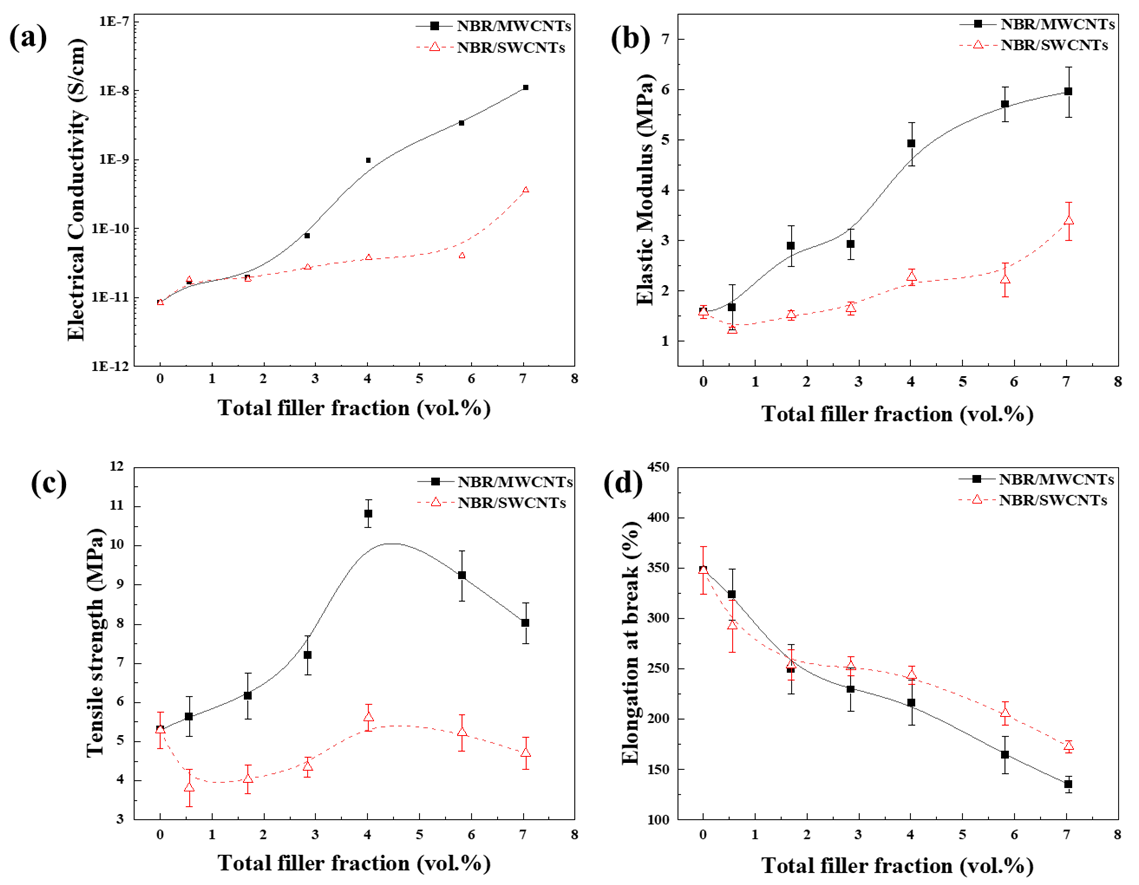
. (<b>a</b>) Electrical conductivity of nanocomposites. Comparisons of (<b>b</b>) elastic modulus, (<b>c</b>) tensile strength and (<b>d</b>) elongation at break of nanocomposites.
The MWCNT nanocomposites demonstrate an increasing trend in electrical conductivity with filler fractions, indicating the establishment of continuous pathways for electron transport within the composites. Tarlton et al. [
31] suggested that smaller agglomerates might even offer advantages to some extent in facilitating charge transport. From our perspective, such agglomerated structure likely contributes to the formation of a segregated network inside the matrix. The use of a 2-roll mill during processing should contribute to the dispersion of MWCNTs within the rubber matrix, thereby enhancing the formation of conductive pathways due to the multi-layered structure of MWCNTs, which allows for more potential electron conduction channels. By contrast, the SWCNT nanocomposites exhibit lower electrical conductivity at similar filler fractions, due to the presence of significant SWCNT agglomerates, as illustrated in b and 3c. The single-walled structure of SWCNTs, while offering high intrinsic conductivity, tends to form tight bundles that limit their dispersion within the matrix. These bundles hinder the establishment of continuous conductive pathways, thereby reducing the overall conductivity.
In both nanocomposites, the percolation thresholds appear to occur at relatively high filler fractions. This can be attributed to the high viscosity of the elastomer matrix, which limits the mobility and dispersion of CNTs, requiring higher filler loading to form conductive networks [
32]. This observation aligns with the existing literature; a percolation threshold of 3 vol.% was reported for epoxy/graphene composites [
33], which is considerably lower than the threshold 19 vol.% observed in EPDM/graphene composites [
34]. This discrepancy might attribute to the differing molecular structures between epoxy resins and elastomers. Epoxy resins possess a rigid and highly crosslinked structure, and upon curing, they convert from a liquidous state to a solid state. These characteristics would enable connectivity of conductive filler particles even at low filler fractions. In contrast, elastomers, owing to their far higher molecular weight and the 2-roll milling process, require higher filler fractions to reach a conductive network.
3.4. Mechanical Properties of Nanocomposites
b–d presents the mechanical properties of NBR/MWCNT and NBR/SWCNT nanocomposites. In b, an increase in the MWCNT fractions leads to a significant enhancement in the elastic modulus of the composite. This improvement can be attributed to the satisfactory dispersion and interaction between the filler and matrix, as observed in the SEM and TEM micrographs. However, in the case of SWCNTs, a slight decline in the elastic modulus is observed at lower filler fractions (0.56–2.84 vol.%); such a phenomenon was occasionally observed for elastomer composites [
35]. This is followed by a subtle increase as the filler fraction rises to higher levels (4.02–7.05 vol.%).
c compares tensile strength between the two groups of nanocomposites. In both cases, the highest tensile strength is evident at 4.02 vol.%, followed by decline at higher filler fractions. This trend is attributed to the presence of agglomerated CNTs, particularly noticeable at higher filler fractions. The presence of more agglomerates leads to defects inducing stress concentration within the matrix, which diminishes the load-bearing capabilities of the composites. The phenomenon is more pronounced in NBR/SWCNT nanocomposites.
Both SWCNTs and MWCNTs were found to reduce the elongation at break of NBR, with no clear difference between these two groups of nanocomposites (d). Adding CNTs to an elastomer typically reduces the elongation at break due to several factors,
i.e., their high aspect ratio, interface interactions and their influence on the crosslinked elastomer matrix. The high aspect ratio results in a significant surface area for interaction with the rubber matrix, which can create interfacial interactions. These interactions restrict the mobility of the elastomer chains, similar to the mechanisms observed in short fiber-reinforced composites. Furthermore, stress concentration points exist at the interface between CNTs and the elastomer matrix, which act as sites for crack initiation and propagation. The presence of CNTs also disrupts the uniformity of the crosslinked network, leading to a more brittle material. As a result, while CNTs enhance the tensile strength and modulus, they concurrently reduce the ability of NBR to elongate, leading to a decrease in elongation at break.
3.5. Swelling and Crosslinking of Nanocomposites
Nitrile butadiene rubber (NBR) is renowned for excellent resistance to water and oils [
21] but exhibits moderate resistance to alcohols. When exposed to toluene, NBR is known to undergo swelling. However, the incorporation of fillers is reported to enhance the swelling resistance by increasing the crosslink density of the elastomer [
34].
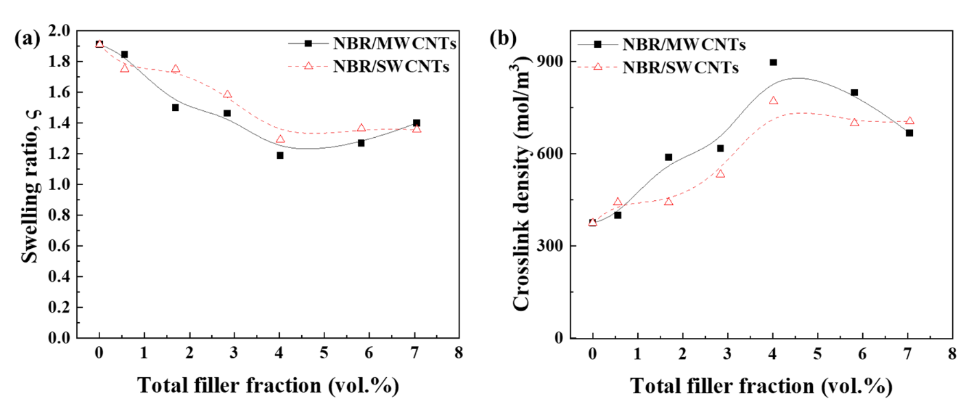
presents values for swelling ratio and crosslink densities for both groups of nanocomposites. a illustrates the swelling ratios of the two groups of nanocomposites, whilst b depicts the crosslink densities. In general, NBR/MWCNT nanocomposites exhibit slightly higher crosslink densities and lower swelling ratios than their SWCNT counterparts. This is likely a result of better dispersion of MWCNTs within the NBR matrix, as indicated in the SEM and TEM analysis. The enhanced dispersion of MWCNTs could facilitate more effective interactions with the elastomer matrix, potentially leading to increased physical crosslinking sites. Consequently, these composites demonstrate lower swelling ratios, as the denser crosslink network restricts the penetration and absorption of solvent molecules. This correlation between filler dispersion and crosslink density in NBR/MWCNT composites highlights the significant impact of nanofiller distribution on the macroscopic properties of the nanocomposites.
. Swelling ratio and crosslink densities for both nanocomposites.
Filler Fraction
(vol.%) |
NBR/SWCNT Nanocomposite |
NBR/MWCNT Nanocomposite |
| Swelling Ratio |
Crosslink Density (mol/m3) |
Swelling Ratio |
Crosslink Density
(mol/m3) |
| 0 |
1.91 |
374.73 |
1.91 |
374.73 |
| 0.56 |
1.75 |
441.50 |
1.85 |
399.24 |
| 1.69 |
1.75 |
441.50 |
1.50 |
587.76 |
| 2.84 |
1.58 |
532.00 |
1.46 |
616.43 |
| 4.02 |
1.29 |
771.07 |
1.19 |
896.64 |
| 5.82 |
1.36 |
699.32 |
1.27 |
798.53 |
| 7.05 |
1.35 |
705.39 |
1.40 |
666.73 |
. Comparison of (<b>a</b>) swelling ratio and (<b>b</b>) crosslink density of nanocomposites.
Between these two groups of nanocomposites, the difference in the swelling ratios is smaller than that in the tensile strength due to different working mechanisms. The interaction between the CNTs and the elastomer matrix is more crucial in determining mechanical properties, while the overall network structure of an elastomer (influenced by crosslink density) plays a more significant role in swelling behaviour. The effectiveness of load transfer from the matrix to the filler in the nanocomposites is likely a key factor in mechanical reinforcement, which depends on the interfacial interaction and the dispersion of CNTs within the matrix. For the swelling properties, the ability of solvent molecules to penetrate the polymer network and interact with the matrix components becomes more relevant, which might be less influenced by the type and dispersion of CNTs.
The results provide partial verification of the study’s hypotheses. The first hypothesis, predicting better electrical conductivity in SWCNT composites, was not fully verified. The second hypothesis, suggesting superior tensile strength and elongation for SWCNT nanocomposites, was partially confirmed, as poor dispersion limited their performance. The third hypothesis, focusing on the impact of dispersion and interaction, was supported, with better MWCNT dispersion leading to improved mechanical and electrical properties.
4. Conclusions
In this study, elastomer nanocomposites containing SWCNTs and MWCNTs were prepared and investigated. The SWCNTs, initially containing ~20 wt.% impurities, were purified prior to modification. Both SWCNTs and MWCNTs were uniformly modified with polyethylene glycol tert-octylphenyl ether (Triton X-100) to improve dispersion before mixing with nitrile butadiene rubber (NBR). SEM and TEM analyses showed that MWCNTs (10–20 nm diameter) were uniformly dispersed in NBR, while SWCNTs (1–2 nm diameter) formed aggregates. NBR/MWCNT nanocomposites exhibited superior mechanical properties, with a tensile strength of 10.8 MPa at 4.02 vol.% compared to 5.6 MPa for NBR/SWCNT composites. Electrical conductivity measurements showed 1119 S/cm for SWCNTs and 21 S/cm for MWCNTs, with NBR/MWCNT composites demonstrating better conductivity and a 139% increase in crosslink density.
The differences in mechanical, electrical and swelling properties are attributed to the dispersion state of the CNTs. MWCNTs dispersed more uniformly than SWCNTs, indicating industrial mixing methods are more effective for MWCNTs. Despite surface modification, the smaller size and lower sensitivity to mechanical shearing of SWCNTs led to poor dispersion, affecting the properties of NBR/SWCNT composites. Notably, the diameter of NBR macromolecules (0.2–0.5 nm) is close to that of SWCNTs, whose single graphene wall with a hollow structure makes them almost as pliable as elastomer macromolecules. This similarity suggests that SWCNTs should be treated as a special type of polymer.
Supplementary Materials
The following supporting information can be found at: https://www.sciepublish.com/article/pii/417, Figure S1: Schematic of elastomer/CNT nanocomposite preparation; Figure S2: Reflux setup for the purification of SWCNTs; Figure S3: Images of (a) two-roll mill, (b) ZWL-III rheometer and (c) curing machine; Table S1: Details of thin films for electrical conductivity; Table S2: Vulcanization recipes for nanocomposite.
Acknowledgments
We gratefully recognize the financial support provided by the ARC Discovery (DP220103275). The authors acknowledge use of the facilities, scientific and technical assistance of Microscopy Australia at the University of South Australia, a facility that is co-funded by the University of South Australia, the State and Federal Governments. P.A expresses gratitude to the University of South Australia for granting the University Presidents Scholarship (UPS). Finally, we extend our sincere appreciation to ChatGPT for its invaluable aid throughout the research and writing phases.
Author Contributions
Conceptualization, P.C.O.A. and J.M.; Methodology, P.C.O.A., H.N. and M.A.; Software, P.C.O.A., H.N. and M.A.; Validation, P.C.O.A. and S.S.C.; Formal Analysis, P.C.O.A., X.S. and J.A.; Investigation, P.C.O.A. and S.S.C.; Resources, J.M.; Data Curation, P.C.O.A. and H.N.; Writing—Original Draft Preparation, P.C.O.A.; Writing—Review & Editing, P.C.O.A. and J.M.; Visualization, P.C.O.A., H.N., M.A., S.S.C., X.S. and J.A.; Supervision, J.M.; Project Administration, J.M.; Funding Acquisition, J.M.
Ethics Statement
Not applicable.
Informed Consent Statement
Not applicable.
Data Availibility Statement
The data supporting findings of this study are available upon reasonable request.
Funding
This research was funded by the ARC Discovery (DP220103275). The authors acknowledge use of the facilities, scientific and technical assistance of Microscopy Australia at the University of South Australia, a facility that is co-funded by the University of South Australia, the State and Federal Governments. P.A expresses gratitude to the University of South Australia for granting the University Presidents Scholarship (UPS). Finally, we extend our sincere appreciation to ChatGPT for its invaluable aid throughout the research and writing phases.
Declaration of Competing Interest
The authors declare that they have no known competing financial interests or personal relationships that could have appeared to influence the work reported in this paper.
References
1.
Araby S, Meng Q, Zhang L, Zaman I, Majewski P, Ma J. Elastomeric composites based on carbon nanomaterials.
Nanotechnology 2015,
26, 112001.
[Google Scholar]
2.
Wang S, Long C, Wang X, Li Q, Qi Z. Synthesis and properties of silicone rubber/organomontmorillonite hybrid nanocomposites.
J. Appl. Polym. Sci. 1998,
69, 1557–1561.
[Google Scholar]
3.
Wu YP, Zhang LQ, Wang YQ, Liang Y, Yu DS. Structure of carboxylated acrylonitrile-butadiene rubber (CNBR)
–clay nanocomposites by co-coagulating rubber latex and clay aqueous suspension.
J. Appl. Polym. Sci. 2001,
82, 2842–2848.
[Google Scholar]
4.
Yu Y, Xu Z, Xu L, Li Y, Liu T, Meng Q, et al. Highly stretchable, sensitive and healable polyurethane-urea/graphene nanocomposite sensor for multifunctional applications.
Thin-Walled Struct. 2024,
198, 111660.
[Google Scholar]
5.
Su X, Yang Z, Cheng R, Luvnish A, Han S, Meng Q, et al. A comparative study of polycarbonate nanocomposites respectively containing graphene nanoplatelets, carbon nanotubes and carbon nanofibers.
Adv. Nanocompos. 2024,
1, 77–85.
[Google Scholar]
6.
La LBT, Nguyen H, Tran LC, Su X, Meng Q, Kuan H-C, et al. Exfoliation and Dispersion of Graphene Nanoplatelets for Epoxy Nanocomposites.
Adv. Nanocompos. 2024,
1, 39–51.
[Google Scholar]
7.
Adu PCO, Aakyiir M, Su X, Alam J, Tran LC, Dai J, et al. Challenges and advancements in Elastomer/CNT nanocomposites with mechanochemical treatment, reinforcement mechanisms and applications.
Smart Mater. Manuf. 2024,
2, 100053.
[Google Scholar]
8.
Yang Z, Qiu A, Ma J, Chen M. Conducting α-Fe₂O₃ nanorod/polyaniline/CNT gel framework for high performance anodes towards supercapacitors.
Compos. Sci. Technol. 2018,
156, 231–237.
[Google Scholar]
9.
Cui K, Chang J, Feo L, Chow CL, Lau D. Developments and Applications of Carbon Nanotube Reinforced Cement-Based Composites as Functional Building Materials.
Front. Mater. 2022,
9, 861646.
[Google Scholar]
10.
Lu S, Shao J, Ma K, Chen D, Wang X, Zhang L, et al. Flexible, mechanically resilient carbon nanotube composite films for high-efficiency electromagnetic interference shielding.
Carbon 2018,
136, 387–394.
[Google Scholar]
11.
Zhang R, Deng H, Valenca R, Jin J, Fu Q, Bilotti E, et al. Carbon nanotube polymer coatings for textile yarns with good strain sensing capability.
Sens. Actuators A Phys. 2012,
179, 83–91.
[Google Scholar]
12.
Vázquez-Martínez Y, Ramírez-Herrera CA, Mondragón M, Elías-Zúñiga A, Elizalde LE. Effect of Single-Walled Carbon Nanotubes on the Cross-Linking Process in Natural Rubber Vulcanization.
Polymers 2022,
15, 126.
[Google Scholar]
13.
Aakyiir M, Tanner B, Yap PL, Rastin H, Tung TT, Losic D, et al. 3D printing interface-modified PDMS/MXene nanocomposites for stretchable conductors.
J. Mater. Sci. Technol. 2022,
117, 174.
[Google Scholar]
14.
Ma J, Yu ZZ, Kuan HC, Dasari A, Mai YW. A new strategy to exfoliate silicone rubber/clay nanocomposites.
Macromol. Rapid Commun. 2005,
26, 830–833.
[Google Scholar]
15.
Xin F, Li L. Effect of Triton X-100 on MWCNT/PP composites.
J. Thermoplast. Compos. Mater. 2013,
26, 227–242.
[Google Scholar]
16.
Vaisman W, Wagner H. The role of surfactants in dispersion of carbon nanotubes.
Adv. Colloid Interface Sci. 2006,
128, 37–46.
[Google Scholar]
17.
Rastogi R, Kaushal R, Tripathi S, Sharma AL, Kaur I, Bharadwaj LM. Comparative study of carbon nanotube dispersion using surfactants.
J. Colloid Interface Sci. 2008,
328, 421–428.
[Google Scholar]
18.
Srivastava SK, Mishra YK. Nanocarbon Reinforced Rubber Nanocomposites: Detailed Insights about Mechanical, Dynamical Mechanical Properties, Payne, and Mullin Effects.
Nanomaterials 2018,
8, 945.
[Google Scholar]
19.
Bokobza L. Mechanical, electrical and spectroscopic investigations of carbon nanotube-reinforced elastomers.
Vib. Spectrosc. 2009,
51, 52–59.
[Google Scholar]
20.
Zaman I, Phan TT, Kuan H-C, Meng Q, La LTB, Luong L, et al. Epoxy/graphene platelets nanocomposites with two levels of interface strength.
Polymer 2011,
52, 1603.
[Google Scholar]
21.
Aakyiir M, Oh J-A, Araby S, Zheng Q, Naeem M, Ma J, et al. Combining hydrophilic MXene nanosheets and hydrophobic carbon nanotubes for mechanically resilient and electrically conductive elastomer nanocomposites.
Compos. Sci. Technol. 2021,
214, 108997.
[Google Scholar]
22.
Aakyiir M, Yu H, Araby S, Ruoyu W, Michelmore A, Meng Q, et al. Electrically and thermally conductive elastomer by using MXene nanosheets with interface modification.
Chem. Eng. J. 2020,
397, 125439.
[Google Scholar]
23.
Hou P, Liu C, Tong Y, Xu S, Liu M, Cheng H. Purification of single-walled carbon nanotubes synthesized by the hydrogen arc-discharge method.
J. Mater. Res. 2001,
16, 2526–2529.
[Google Scholar]
24.
Dillon AC, Gennett T, Jones KM, Alleman JL, Parilla PA, Heben MJ. A simple and complete purification of single-walled carbon nanotube materials.
Adv. Mater. 1999,
11, 1354–1358.
[Google Scholar]
25.
Hu H, Zhao B, Itkis ME, Haddon RC. Nitric Acid Purification of Single-Walled Carbon Nanotubes.
J. Phys. Chem. B 2003,
107, 13838–13842.
[Google Scholar]
26.
Yaya A, Ewels C, Wagner P, Suarez-Martinez I, Tekley AG, Jensen LR. Purification of single-walled carbon nanotubes.
Eur. Phys. J. Appl. Phys. 2011,
54, 10401.
[Google Scholar]
27.
Zimmerman JL, Bradley RK, Huffman CB, Hauge RH, Margrave JL. Gas-Phase Purification of Single-Wall Carbon Nanotubes.
Chem. Mater. 2000,
12, 1361–1366.
[Google Scholar]
28.
Tomova A, Gentile G, Grozdanov A, Errico M, Paunović P, Avella M, et al. Functionalization and Characterization of MWCNT Produced by Different Methods.
Acta Phys. Pol. A 2016,
129, 405.
[Google Scholar]
29.
Adhikari S, Jaishi KP, Pradhan Joshi L, Shrestha SP. Dispersion of single-walled carbon nanotubes in water in presence of Direct Current field.
Indian J. Phys. 2022,
97, 61–66.
[Google Scholar]
30.
Filchakova M, Saik V. Single-walled carbon nanotubes: Structure, properties, applications, and health & safety. Tuball 2021. Available online: https://tuball.com/articles/single-walled-carbon-nanotubes. (accessed on 10 February 2024).
31.
Tarlton T, Sullivan E, Brown J, Derosa PA. The role of agglomeration in the conductivity of carbon nanotube composites near percolation.
J. Appl. Phys. 2017,
121, 085103.
[Google Scholar]
32.
Ata S, Nguyen Thi TB, Kolaric I. Effect of matrix polymer viscosity on nanofiller exfoliation during compounding.
Polymer Bulletin 2022,
79, 9685–9696.
[Google Scholar]
33.
Han S, Chand A, Araby S, Cai R, Chen S, Kang H, et al. Thermally and electrically conductive multifunctional sensor based on epoxy/graphene composite.
Nanotechnology 2019,
31, 075702.
[Google Scholar]
34.
Araby S, Zaman I, Meng Q, Kawashima N, Michelmore A, Kuan HC, et al. Melt compounding with graphene to develop functional, high-performance elastomers.
Nanotechnology 2013,
24, 165601.
[Google Scholar]
35.
Araby S, Wang CH, Wu H, Meng Q, Kuan HC, Kim NK, et al. Development of flame-retarding elastomeric composites with high mechanical performance.
Compos. Part A Appl. Sci. Manuf. 2018,
109, 257–266.
[Google Scholar]