Offshore wind power structures are among the most complex “high-rise” structures. Their safe operation is subject to long-term influences and threats from strong typhoons, massive waves, ocean currents (and ice), and the dynamic loads generated by large wind turbines. Overcoming the challenges of strong coupling between wind, wave currents, foundation, structure, and turbine requires advancements in analytical theory and design methods. Developing offshore wind power foundation systems that are adaptable to various types of foundations is fundamental and crucial for achieving safe, efficient, high-quality, and low-cost offshore wind power development. Based on the different support technologies for offshore wind turbines, the foundations of offshore wind turbines can currently be classified into two main categories: fixed-bottom and floating.
3.1. Fixed Bottom Foundation Types
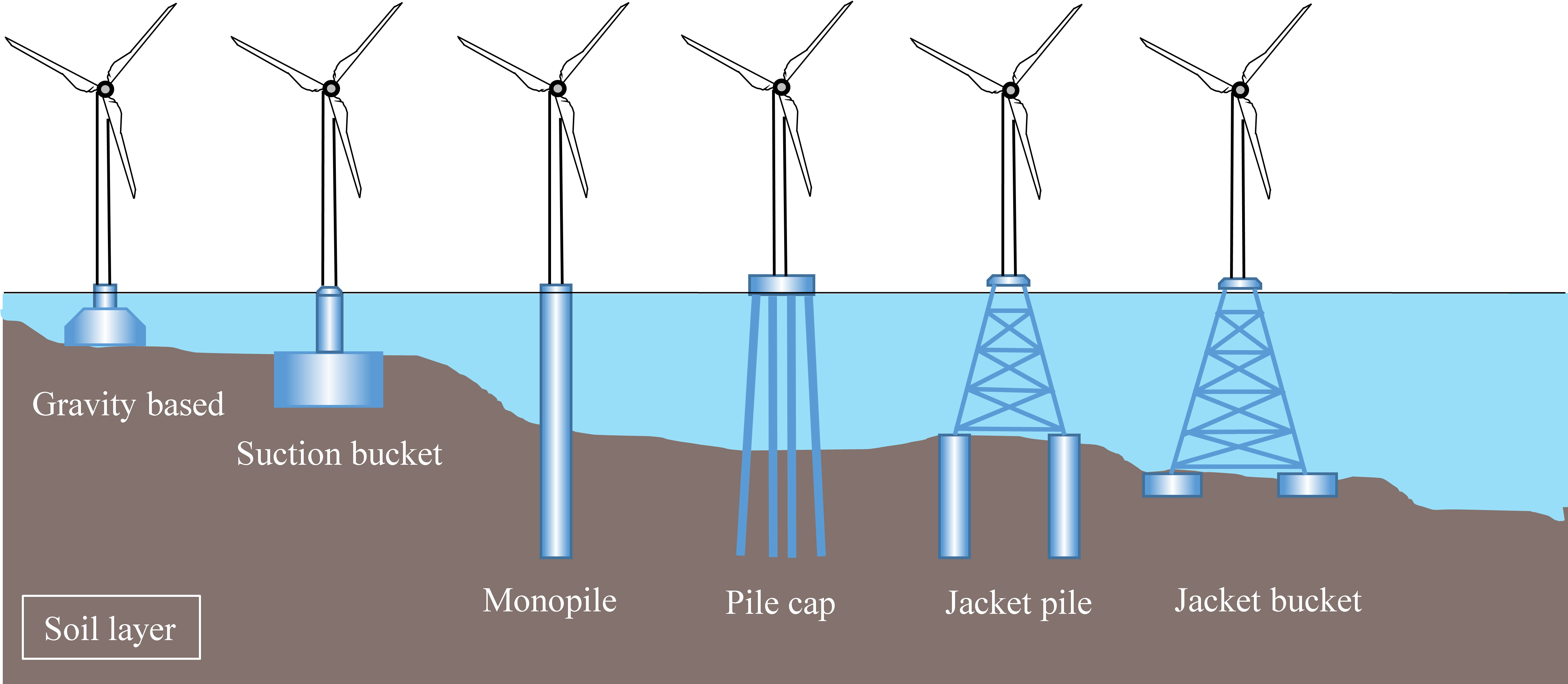
The foundation structure of offshore wind power is critical for ensuring the stable and safe operation of wind turbines. Offshore wind power structures must withstand extreme natural conditions such as strong winds, waves, ocean currents, and ice. Therefore, their design must take into account the complex marine environment, foundation-bearing capacity, and the dynamic loads imposed by wind turbines. In recent years, significant progress has been made in the research and technological development of offshore wind power foundation structures. Fixed-bottom foundations, categorized based on the type of base and supporting structure, are primarily divided into the following five types: Gravity-based, Suction bucket, Monopile, Pile cap, and Jacket, as shown in .
. Common types of fixed-bottom offshore wind power foundations.
The gravity-based foundation [
5] is the earliest applied offshore wind turbine foundation structure type. It is commonly made of a concrete gravity base structure, which resists the loads from wind turbines and various environmental forces through self-weight. Typically, precast reinforced concrete gravity base structures are used with internal ballast materials such as sand, gravel, slag, or concrete. Due to limitations in construction conditions and economic factors, this type of structure was commonly adopted during the early stages of offshore wind energy development, such as at the world’s first offshore wind farm, Vindeby [
6]. Gravity-based foundations are generally suitable for shallow waters with depths of up to 10 m. In addition, for shallow water areas where pile foundations are not feasible, gravity-based foundations are recommended, such as at Denmark’s Nysted Wind Farm [
7].
The bucket foundation [
8] has a shape similar to an inverted bucket, with a relatively shallow burial depth and a large diameter. It is typically installed by vacuum-assisted penetration. This foundation type offers advantages such as simple manufacturing, easy transportation, and fast construction. It is generally suitable for water depths ranging from 0 to 25 m. Currently, this type of foundation is used in several offshore wind farms in China, including those in Jiangsu’s Qidong, Xiangshui, Dafeng, and Rudong, as well as in Guangdong’s Guishan and Yangjiang, Fujian’s Changle and Putian, and Dalian’s Zhuanghe.
The monopile foundation for offshore wind turbines is similar to that used on land. It is the simplest and most widely applied structure, composed of welded steel pipes made from rolled steel plates. This type of foundation is suitable for non-rocky seabed areas with water depths of up to 30 m. Due to limitations in construction conditions, earlier applications typically used steel pipes with diameters of less than 4 m, such as those used in Denmark’s Horns Rev I wind farm [
9]. As construction technology has advanced and the capacity of individual wind turbines has increased, monopile foundations are now being developed with larger diameters. In 2012, the Jiangsu Rudong offshore wind farm in China adopted a large-diameter steel monopile with a diameter of 5.2 m, which was the largest steel monopile in Asia at the time [
10].
The pile cap foundation [
11] is a foundation type and substructure independently developed by China, suitable for soft soil foundations. It consists of several piles and a cap located above the sea level (or above the scour line), forming a pile foundation structure. This type of foundation is commonly used in large bridges and coastal construction projects and is currently being applied to offshore wind turbine foundations. It consists of a base pile at the bottom and a rigid cap at the top. The pile cap foundation has advantages such as high structural stiffness, good collision resistance, ease of construction, and high resistance to overturning loads. It is generally suitable for water depths ranging from 0 to 20 m. Currently, the high-pile cap foundation structure is used in China’s Donghai Bridge [
12] and the Zhoushan-Putuo offshore wind farm in Zhejiang.
The jacket foundation [
13] is commonly used in deep-sea oil drilling platforms. When the water depth exceeds 30 m, the cost of using a monopile foundation increases significantly, and the jacket foundation can be used as an alternative to the monopile foundation. This foundation type is now being promoted for offshore wind turbine structures. The substructure uses a truss structure, which interconnected steel pipes to form a spatial prismatic structure. The leading pipe at the bottom of the foundation is equipped with a sleeve connecting to the pile foundation. The connection between the jacket sleeve and the pile or bucket foundation is achieved through grouting. The foundation consists of 3–4 steel pipe piles or suction buckets, and the jacket foundation is generally suitable for water depths of 20 to 40 m. Currently, this foundation type is used in the UK’s Thornton Bank Phase II wind farm, the Thornton Bank Phase II wind farm in Belgium, and the Guishan wind farm in Guangdong, China [
14]. The jacket foundation has advantages such as high strength and low installation noise but requires a large amount of steel.
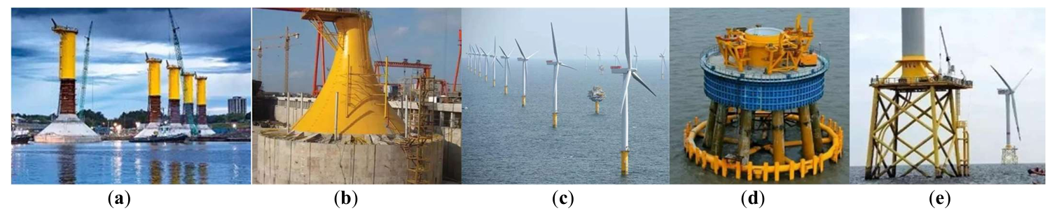
The characteristics of the five types of fixed bottom foundations can be summarized in , and they have been applied internationally in the wind energy sector, as shown in . In China, due to the planning characteristics of the coastline and geographical conditions, most of the completed and under-construction wind projects are concentrated in shallow sea areas, with large-diameter steel pipe piles becoming the dominant foundation type. Flexible piles with diameters between 1.5 m and 2 m mainly appear in the form of high-capacity pile groups. In comparison, semi-rigid or rigid piles larger than 2 m are mainly used as monopile foundations. For example, in June 2010, China’s first national-level offshore wind power demonstration project, the Shanghai Donghai Bridge Wind Farm, was completed and successfully connected to the grid [
10]. This project used high-capacity steel pipe pile foundations with diameters between 1.5 m and 2.0 m and pile lengths between 60 m and 80 m. From 2015 to the present, the piles used in the Jiangsu Xiangshui Wind Power Project are high-capacity steel pipe piles, with diameters between 1.8 m and 2.0 m and pile lengths between 70 m and 80 m. In June 2010, the construction of the “Rudong 30 MW Tidal Zone Experimental Offshore Wind Farm Project” began, with pile diameters primarily ranging from 5 m to 6.5 m for large-diameter steel pipe piles [
10]. In 2011, the “Longyuan Jiangsu Rudong 150 MW Offshore (Tidal Zone) Demonstration Wind Farm” began construction, where the selected steel pipe piles also had diameters ranging from 5 m to 6 m. Between 2014 and 2015, the China General Nuclear Power Group’s 150 MW Rudong Offshore Wind Farm successfully used large-diameter steel pipe piles with diameters of 6.6 m and pile lengths of 93 m. By September 2015, 20 ultra-large-diameter monopile foundations had been successfully installed for this project. From 2015 to the present, the China Power Investment Corporation’s Binhai North H1#100MW Offshore Wind Project, with water depths ranging from 6 m to 13 m, also used monopile foundations with diameters between 4.6 m and 6.8 m, with average pile lengths of about 67.0 m and embedment depths of about 53 m. Between 2017 and 2019, the Guohua Dongtai Phase IV (H2) 300MW Offshore Wind Project primarily used large-diameter steel pipe piles with diameters ranging from 6 m to 6.5 m and embedment depths of 30 m to 32 m. From 2016 to 2020, Huaneng Wind Power’s Phase I and II primarily used large-diameter steel pipe piles with diameters ranging from 6 m to 6.5 m and embedment depths of 30 m to 34 m. In 2024, China Dongfang Electric’s largest 26 MW turbine will be supported by a fixed bottom foundation and officially launched in Fuzhou, Fujian. The seawater depth in the above areas is relatively shallow, with seabed foundations consisting of a mixture of silty soils, silty sand, and fine sand, with considerable coverage depth. Using large-diameter steel pipe piles offers significant advantages. Most steel pipe piles have their tips embedded in soil layers with good bearing capacity, which serve as the bearing layer, as they cannot reach bedrock. The tip has free boundary conditions. In the coastal regions of Fujian, due to the shallow burial depth of the bedrock, some piles are embedded in the bedrock at the bottom, where the pile bottom can be considered to have fixed boundary conditions.
. Common types of fixed-bottom offshore wind power foundations. (<b>a</b>) Blyth, UK; (<b>b</b>) Three gorges Xiangshui, China; (<b>c</b>) London Array, UK; (<b>d</b>) Donghai Bridge, China; (<b>e</b>) Alpha Ventus, Germany.
.
Characteristics of fixed-bottom foundations for offshore wind turbines.
| Foundation Type |
Overview |
Applicable Water Depth |
Structure |
Classification |
Advantages |
Advantages |
| Gravity-based foundation |
Earliest application |
<10 m |
Prefabricated reinforced concrete caisson structure, filled with sand, gravel, slag, or concrete ballast material |
Prefabricated concrete caissons and steel structure caissons |
Good stability |
High foundation requirements; seabed treatment needed during installation; sensitive to seabed scour |
| Suction bucket foundation |
Prefabricated on land, submerged by water suction, and removed by water injection |
<25 m |
Composed of a cylindrical body and an extending section |
Prestressed reinforced concrete structure and steel structure |
Low cost, fast construction speed |
High precision required during construction |
| Monopile foundation |
Simplest structure, most widely used |
<30 m |
Composed of welded steel pipes made from rolled steel plates |
Monopile with transition section, monopile without transition section |
Simple structure, quick construction, relatively low cost |
Low stiffness, low natural frequency, significantly affected by seabed scour, high requirements for construction equipment |
| Pile Cap foundation |
Independently developed lower structure and foundation type in China, suitable for soft soil foundations |
<20 m |
Composed of several piles and a pile cap located above sea level (or above the scoured area) |
Conventional pile cap foundation, high pile cap foundation |
High structural stiffness, good stability, good collision resistance, mature construction process |
Long construction period, unsuitable for deeper waters |
| Jacket foundation |
Based on offshore oil platform technology |
20 m~40 m |
The lower structure adopts a truss structure, with the bottom connected to piles or bucket foundations |
Jacket pile foundation, Jacket bucket foundation |
High stiffness, good stability |
Complex structural forces, potential fatigue issues, higher construction and maintenance costs |
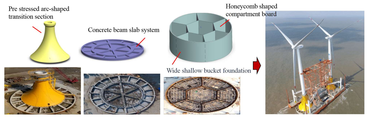
As the capacity and power of offshore wind turbines increase, the foundation’s water immersion depth gradually increases, and the traditional foundations’ anti-tilt ability becomes insufficient. This has led to the emergence of other support structures. Based on different foundation conditions, the wind energy team at Tianjin University proposed the “giant multi-compartment offshore wind turbine bucket foundation structure system”. This structure greatly improves the foundation’s anti-tilt ability through a design with a large diameter and adjustable skirt length, providing strong support for offshore wind turbine installation. The “giant multi-compartment offshore wind turbine bucket foundation structure system” (shown in ) consists of an upper section as a transition segment connecting the tower bucket, which transfers the wind turbine load to the foundation. The lower part includes a top cover and the compartment skirt structure embedded into the seabed [
15]. The foundation diameter ranges from 30 m to 45 m, with skirt lengths between 5 m and 20 m. This “wide and shallow” structure provides significant anti-tilt capacity, which is essential for the “tree-planting” method of installing turbines as a whole [
8,
16]. In 2010, the single bucket multi-compartment composite bucket foundation prototype for a 2.5 MW wind turbine was successfully installed in the Qidong Sea area of Jiangsu, marking the first application of the multi-compartment bucket in China’s wind power industry [
16]. In 2017, the Jiangsu Xiangshui offshore wind farm achieved one-step installation of the foundation, tower, and turbine, with a total installation time of only 8 h per turbine, signaling the maturity of the one-step installation technology for the multi-compartment bucket [
17,
18]. Currently, multi-compartment buckets have been mass-produced, with foundations spread across the South China Sea and Yellow Sea, and the foundation types are gradually developing toward larger sizes and greater diversity.
. Giant multi-compartment offshore wind turbine monopile foundation type.
In recent years, with the frequent occurrence of extreme weather events and the setting of “carbon peak and carbon neutrality” goals, the demand for clean energy has become a major focus. As tidal zones and nearshore areas gradually become saturated, the construction of wind farms moving into deeper seas has become inevitable. The shift from land to sea, from shallow to deep waters, and from fixed bottom foundations to floating platforms will become the development trend of offshore wind power. In shallow sea areas with a water depth of less than 50 m, fixed bottom foundation structures are typically used. However, in deep-sea areas where the water depth exceeds 50 m, the cost of fixed bottom foundations increases sharply, making them difficult to implement [
19,
20]. Compared with fixed-bottom foundations, floating foundation structures offer advantages such as better operability, ease of removal, and recyclability. As a result, floating structures have become the preferred foundation type for offshore wind farms in deep and remote sea areas.
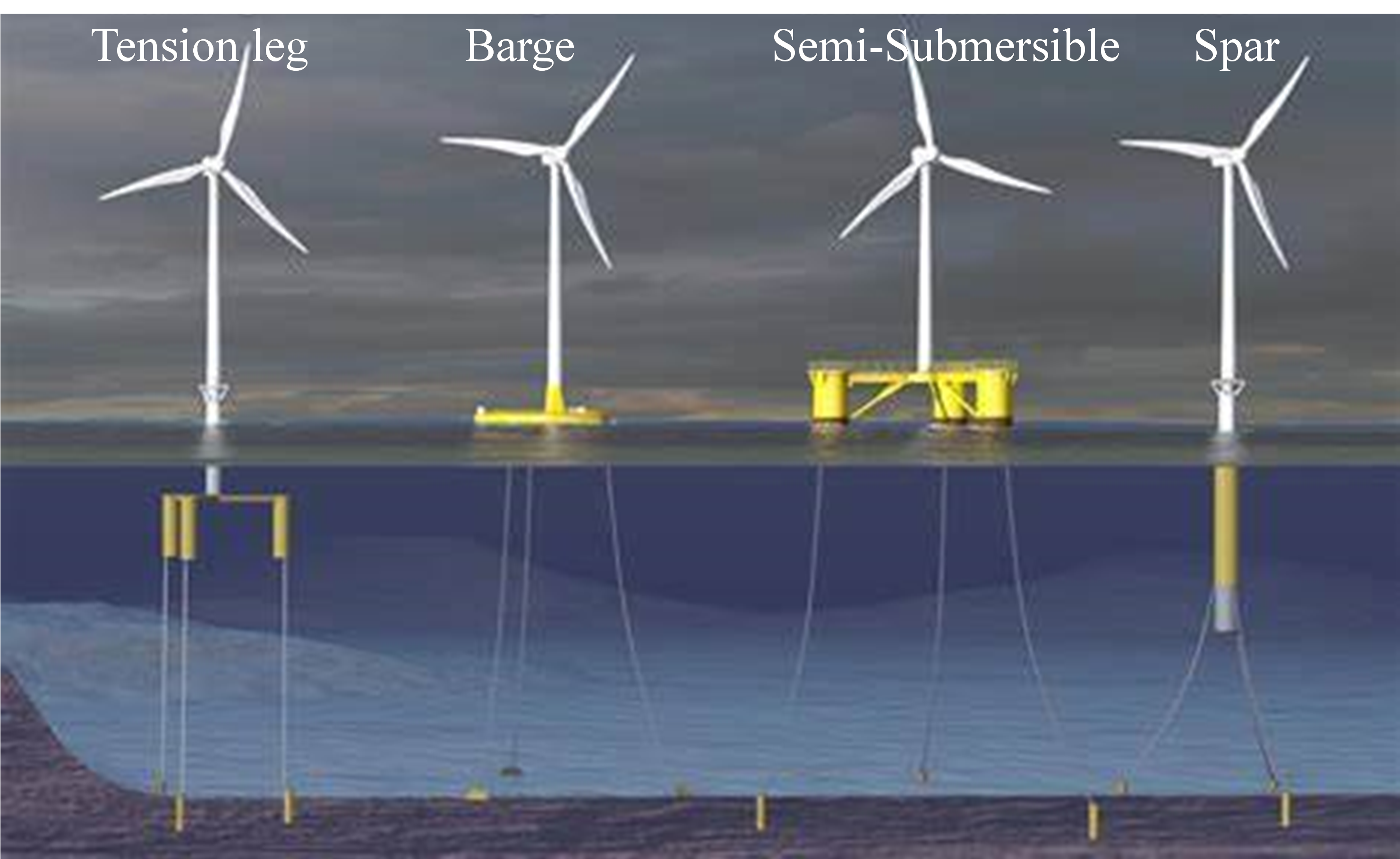
Unlike nearshore wind turbines, floating wind turbines are not fixed to the seabed with monopiles or jackets but instead float on the sea surface. The supporting system of floating wind turbines mainly consists of the seabed floating foundation structure, mooring system, and anchoring structure [
21]. The key design tasks are flotation, mooring, and anchoring. Flotation addresses the issue of the turbine floating on the sea surface. Based on the type of foundation, floating wind power can be divided into four types: Tension Leg Platform (TLP), Barge, Semi-Submersible, and Spar, as shown in . Demonstration projects for all four types have been completed or are under construction abroad [
22]. Mooring ensures the platform does not tilt under various operating conditions and sea states. The mooring lines are typically of three types: catenary mooring, tension mooring, and mooring line mooring [
23,
24,
25]. The mooring system primarily comprises winches, cable guides, mooring ropes, and gravity buoyancy attachments. Anchoring addresses the issue of securing the turbine at the design installation site. The seabed anchoring structures typically have four types: drag anchor, pile anchor, suction bucket anchor, and gravity anchor [
26,
27,
28].
Tension-leg foundations have the advantages of low structural weight, fewer moving parts in the wind turbine, and excellent stability. However, their installation requires a specially designed barge, making it more difficult. Additionally, tension-leg foundations’ mooring and anchoring systems are subject to higher loads.
Barge foundations are generally made of concrete and operate similarly to ships. They have a large waterline area, a shallow draft, and excellent stability. The construction, transportation, and installation are convenient. They are typically suitable for installation in waters deeper than 30 m. However, their unique design makes barge-type foundations respond with significant rolling and pitching motion in rough seas, making them more suitable for calm seas.
Semi-submersible foundations are flexible in terms of water depth and can operate in shallow water areas. They have lower transportation costs compared to jacket and tension-leg foundations and can be refurbished in port. This is the most widely used floating foundation type. However, semi-submersible foundations require high structural quality to provide sufficient buoyancy and stability, which increases the foundation cost. Additionally, more welding joints and complex steel structures raise manufacturing difficulties.
. Common floating foundation types for offshore wind turbines.
Spar foundations have advantages such as being lightweight, having a simple structure, good stability, and low cost, making them one of the most mature technologies. However, they have specific water depth requirements (typically used in waters deeper than 100 m). The large draft limits the ability to tow the jacket-type foundation back to port for maintenance, and its large size adds difficulty to installation and transportation.
In 1972, HERONEMUS [
29] first proposed the concept of floating offshore wind turbines. Due to the technological and cost limitations at the time, it was not developed for engineering applications. It was not until 2009, when Equinor, a Norwegian oil and gas company, invested in the project, that the world’s first floating wind turbine, “Hywind”, was completed and put into operation. This turbine had a capacity of 2.3 MW, a rotor diameter of 82.4 m, a hub height of 65 m, and weighed 11,500 t.
Since the commissioning of the first floating wind turbine, floating wind turbines have been developed worldwide, as shown in . Europe has been at the forefront of developing offshore wind technology. With the gradual increase in single-turbine capacity, the potential for the development of floating offshore wind energy has been proven.
.
Parameters of floating offshore wind power in China [30].
| Country |
Commissioning Year |
Wind Farm Name |
Water Depth /m |
Single Turbine Capacity/MW |
Foundation Type |
Turbine Model |
Number of Turbines |
| Norway |
2009 |
Hywind Demo |
10 |
2.3 |
Spar |
2.3MW (SGRE) |
1 |
| UK |
2017 |
Hywind Scotland |
95~120 |
6.0 |
Spar |
SWY6.0 MW-154
(SGRE)
|
5 |
| France |
2019 |
Floatgen |
33 |
2.0 |
Semi-Submersible |
V80-2.0MW
(MHI Vestas)
|
1 |
| Japan |
2019 |
Hibiki Nada |
55 |
3.2 |
Semi-Submersible |
3.2MW(Aerodyn) |
1 |
| Portugal |
2020 |
WindFloat
AtlanticⅠ
|
100 |
8.4 |
Semi-Submersible |
V164-8.4MW
(MHI Vestas)
|
2 |
| UK |
2021 |
Kincardine |
60~80 |
10.0 |
Semi-Submersible |
V164-9.6MW
(MHI Vestas)
|
5 |
| Norway |
2022 |
Hywind Tampen |
260~300 |
8.0 |
Spar |
SWT 8MW-154(SGRE) |
11 |
| France |
2022 |
Eollennes Florrantes de Groix |
70 |
9.5 |
TLP |
V164-9.5MW
(MHI Vestas)
|
3 |
| France |
2023 |
Eolmed |
60 |
10.0 |
Barge |
V164-10MW
(MHI Vestas)
|
3 |
| France |
2023 |
Provence Grand Large |
100 |
9.5 |
TLP |
SWT-8.4MW
(MHI Vestas)
|
3 |
| France |
2023 |
EFGL |
70~100 |
10.0 |
Semi-Submersible |
V164-10MW
(MHI Vestas)
|
3 |
In 2013, China launched the floating wind power project under the National 863 Program. During this period, Xiangdian Wind Energy developed a 3 MW reinforced concrete floating foundation, while Goldwind proposed a 6 MW semi-submersible platform solution. In 2016, as part of the Green Energy demonstration project, Green Energy Company, in collaboration with the Shanghai Institute of Survey and Design, Shanghai Jiao Tong University, and Shanghai Electric, conducted research on two solutions: a 3.6 MW tension leg platform and a 6 MW semi-submersible platform. However, the demonstration project was not realized. The rapid development period of floating technology and patent applications in 2019. The first floating demonstration project at sea in China, the Three Gorges “Leading”, was installed in 2021. By 2030, the cumulative installed capacity of global floating offshore wind power will reach 16.5 GW. By 2036, floating offshore wind power will enter the stage of commercialization with new installed capacity reaching GW level.
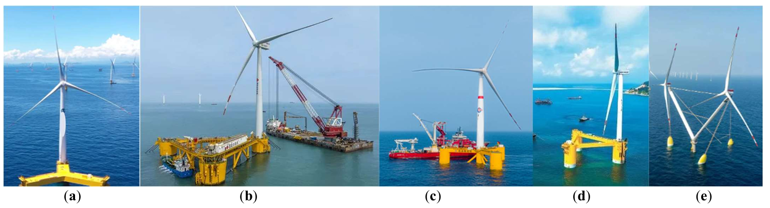
China’s floating offshore wind power technology is largely synchronized with international advancements and is currently in the small-scale demonstration phase, either with single or multiple turbines [
29]. As of 2024, China has five floating offshore wind turbines, as shown in and .
.
Parameters of floating offshore wind power in China.
| Project |
Commissioning Year |
Location (Sea Area) |
Water Depth/m |
Offshore Distance /km |
Single Turbin Capacity /MW |
Foundation Type |
Steel Consumption per MW/t |
Steel Consumption per MW/
(10,000 RMB) |
| Three Gorges Leading |
2021 |
Yangjiang, Guangdong |
30 |
30 |
5.5 |
Semi-Submersible |
1.023 |
5.91 |
| CSSC Fu Yao |
2022 |
Zhanjiang, Guangdong |
65 |
15 |
6.2 |
Semi-Submersible |
645 |
5.63 |
| CNOOC Guanlan |
2023 |
Wenchang, Hainan |
120 |
136 |
7.25 |
Semi-Submersible |
552 |
4.87 |
| China Energy Gongxiang |
2023 |
Putian, Fujian |
35 |
14 |
4 |
Semi-Submersible |
|
|
| Ming Yang Tiancheng |
2024 |
Yangjiang, Guangdong |
45 |
70 |
16.6 |
Semi-Submersible |
|
|
. Floating offshore wind power demonstration projects in China. (<b>a</b>) Three Gorges Leading; (<b>b</b>) CSSC Fu Yao; (<b>c</b>) CNOOC Guanlan; (<b>d</b>) China Energy Gongxiang; (<b>e</b>) Ming Yang Tiancheng.
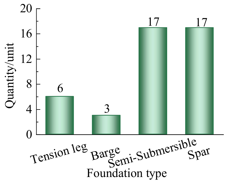
An analysis of the foundation types for the 43 floating wind turbines surveyed reveals the number of installations for different types of floating foundations, as shown in . The characteristics of the floating foundations are presented in .
. Number of different foundation types.
.
Characteristics of different types of floating foundations.
| Foundation Type |
Environmental Conditions |
Installation |
Applicable Water Depth |
Suitability for Turbine |
Technological Maturity |
Potential for Mass Production |
| Barge |
Mild |
Simple |
Unrestricted |
General |
High |
General |
| Spar |
Harsh |
Complex |
>100 m |
Good |
High |
General |
| Semi-submersible |
Harsh |
Simple |
Unrestricted |
Good |
High |
General |
| TLP |
Harsh |
Complex |
Unrestricted |
Good |
Low |
High |
As shown in
, floating offshore wind power currently mainly relies on Spar and semi-submersible foundations. The Spar is easy to construct but complicated to install, requiring deep waters for stabilization operations and integration of the wind turbine and foundation. It is unsuitable for developing industrial chains, shipping routes, and sea area conditions in China. Due to semi-submersible mature technology, superior hydrodynamic performance, and the fact that the foundation construction, assembly, outfitting, and commissioning, as well as the installation of the wind turbine, can all be completed at the dock before being towed out and deployed, the semi-submersible platform is expected to be the main foundation type for floating wind power. The TLP wind turbine has in-place performance similar to fixed wind turbines, with higher overall power generation. The corresponding mooring line coverage area is smaller, the layout is simpler, and the cables have better fatigue resistance, making arranging the power transmission direction easier. Overall, semi-submersible and TLP wind turbines are China’s main development directions for floating wind power.
To better reflect the technological maturity level of offshore wind turbine foundations, the Technology Readiness Level (TRL 1-9) is used to map the maturity of foundation types, as shown in
.
.
Maturity mapping of fixed and floating foundation types.
| Maturity Level |
Fixed Bottom Foundation Types |
Floating Foundation Types |
TRL 1
Concept proposed, but no experimental validation yet.
|
|
|
TRL 2
Preliminary technical concept formed, laboratory validation begins
|
|
|
TRL 3
Key functions validated in a laboratory environment
|
|
|
TRL 4
Components or subsystems integrated and validated in a laboratory environment
|
|
|
TRL 5
Components or subsystems validated in a simulated environment
|
|
|
TRL 6
System prototype validated in relevant environment
|
Bucket foundation |
TLP, Barge |
TRL 7
System prototype validated in an actual environment
|
Gravity-based foundation, Pile cap foundation |
Spar |
TRL 8
System completed and tested, ready for commercialization
|
Jacket foundation |
Semi-Submersible |
TRL 9
Technology successfully applied in real-world scenarios, commercialization completed
|
Monopile |
|
shows that the monopile foundation technology is relatively mature and is currently the most widely used foundation in offshore wind power. The other foundations are mainly in the stage between technical development and commercialization. They are insufficient for practical application and require further research for specific environments.
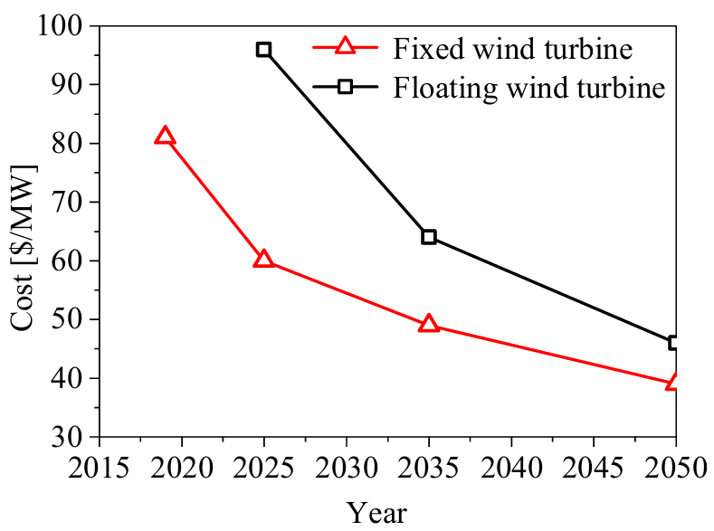
From the perspective of cost, analyzing the foundation types, the high construction cost of floating wind power is the main constraint on its commercialization process. Det Norske Veritas (DNV) used industrial cost estimation to show that floating designs are competitive at water depths exceeding 50 m in terms of the Levelized Cost of Energy (LCOE) compared to fixed-bottom foundations. When project investments exceed 50 million euros, the cost competitiveness index of floating wind increases. However, although floating wind turbines are more competitive than fixed wind turbines at water depths greater than 50 m, the technology is still not commercially competitive compared to other energy sources.
shows the cost variation trends of fixed and floating wind turbines [
31].
. Cost variation of fixed and floating wind turbines.
As shown in
, with the advancement of technology and resource integration, the construction cost of floating wind turbines is gradually decreasing. However, it will not fall below the cost of fixed-bottom turbines. The cost difference between the two is expected to converge by 2050. The key to reducing the cost of floating wind power is the use of larger turbines, larger wind farms, significant technological development, and the creation of highly cost-competitive supply chains. Among these, the cost of foundations accounts for a significant share of the overall offshore wind farm construction. The cost of fixed-bottom wind turbine foundations accounts for 24%, while the cost of floating wind turbine foundations accounts for 17%. Compared to fixed-bottom foundations, floating wind foundations do not require seabed preparation or piling processes before installation. Therefore, the proportion of foundation costs is relatively smaller for floating wind. However, the anchoring system represents a larger proportion of the floating wind construction cost, offering substantial potential for cost reduction.
Offshore wind construction vessels, as essential carriers for offshore wind farm construction, have become indispensable foundational equipment for marine specialized operations. Early wind power construction equipment was primarily based on the modification of traditional offshore construction vessels, which resulted in low construction efficiency and limited application scenarios. With the development and expansion of the offshore wind industry, more investors have recognized the growth potential of specialized vessels, leading to an increase in the construction of vessels specifically designed for offshore wind farm construction. The development of wind power specialized vessels has rapidly advanced, construction processes have gradually been optimized, and construction efficiency has significantly improved. However, as offshore wind power moves toward deeper waters and the rapid growth of individual turbine capacities, the pace of innovation in vessel performance will limit the rapid development of offshore wind power. The industry is increasingly favoring larger, smarter, and more customized vessels.
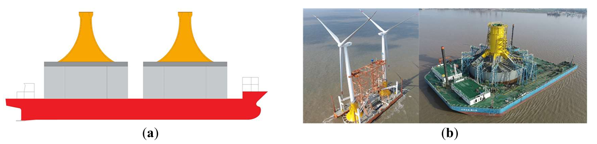
The installation technology of offshore wind power is a critical link in ensuring wind turbines’ safe and efficient operation. Offshore wind power installation often takes place under complex sea conditions, and traditional installation technologies face significant challenges in deep-water areas or extreme marine conditions. In recent years, with technological advancements, a series of innovative installation techniques and equipment have been proposed and applied. Among these, one of the most important breakthroughs is the introduction of the “tree planting” integrated floating transport and installation technology. This technology involves floating and transporting the bucket foundation, tower, and turbine as a single unit using air-supported flotation transport. The world’s first U-type and U-K-type offshore wind turbine monopile foundation-tower-turbine integrated floating transport and installation equipment was developed (), which reduces equipment investment by approximately 70% compared to traditional construction equipment. It significantly improves installation efficiency and allows installation in relatively harsh sea conditions. Meanwhile, regarding turbine lifting in complex sea conditions, this technology effectively addresses the challenge of lifting turbines on ultra-soft foundations [
8,
18,
32].
. Bucket foundation-tower-unit integrated floating transportation and installation technology. (<b>a</b>) Traditional dry tow floating transportation; (<b>b</b>) New ship-under air-floating op towing technology.
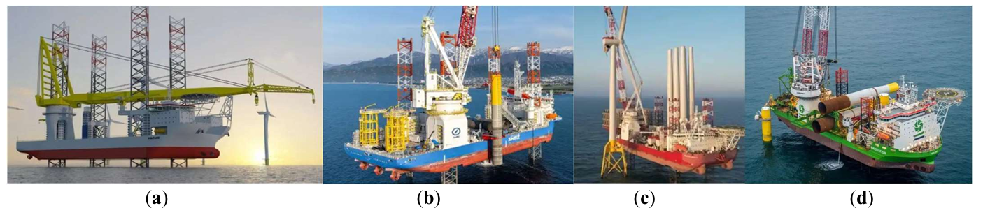
Europe, as one of the earliest regions to enter the offshore wind power industry, has developed specialized wind turbine installation platforms after decades of exploration and research. Other countries have also accelerated the development and manufacturing of jack-up wind turbine installation vessels in an effort to gain control over the offshore wind installation market. As early as the 1950s, a company in the United States developed and manufactured the world’s first self-propelled jack-up platform, which was primarily used for offshore drilling and oil extraction services. It was not until 1991, when Denmark built the world’s first offshore wind farm, countries worldwide began to develop offshore wind power. By 2019, the countries with the highest cumulative installed offshore wind capacity were the United Kingdom, Germany, China, Denmark, Belgium, and the Netherlands. These countries are also the leaders in the development and construction of wind turbine installation vessels, such as the UK’s MPI, Seajacks, Denmark’s A2SEA, and the Netherlands’ Jack-up Barge companies [
33]. As of August 2020, more than 700 vessels had participated in offshore wind power projects globally. Among these, 52 specialized offshore wind installation vessels have both jack-up and self-propulsion capabilities, with 31 vessels having a Safe Working Load (SWL) greater than 800 t. In addition, there are currently 14 self-elevating platforms under construction, with 9 of them having a SWL greater than 800 t [
34]. Some of the major third-generation large self-elevating offshore wind power operation platforms abroad are shown in and .
.
Major third-generation large self-elevating offshore wind farm platforms.
| Ship Owner |
Ship Name |
Technology Type |
Main Dimensions
/m × m × m |
Maximum Operating Water Depth/m |
Lifting Capacity
/t |
| JanDeNul |
Voltaire |
Lifting Capacity |
169.3 × 60 × 14.6 |
80 |
3000 |
| Shimizu |
NG14000X |
Lifting Capacity |
142 × 50 × 11 |
65 |
2500 |
| Seajack |
Scylla |
Lifting Capacity |
139 × 50 × 11 |
65 |
1500 |
| GeoSea |
Innovation |
Self-elevating |
147.5 × 42 × 11 |
50 |
1500 |
| Swire Pacific Offshore |
Pacific Osprey |
Self-elevating |
155.6 × 49 × 10.4 |
65 |
1425 |
Sea Energy
Sea Installer
Sea Power
|
NG9000 |
Self-elevating |
123.55 × 39 × 9 |
45 |
1000 |
. Jack-up offshore installation vessel. (<b>a</b>) Voltaire; (<b>b</b>) NG14000X; (<b>c</b>) Scylla; (<b>d</b>) Innovation.
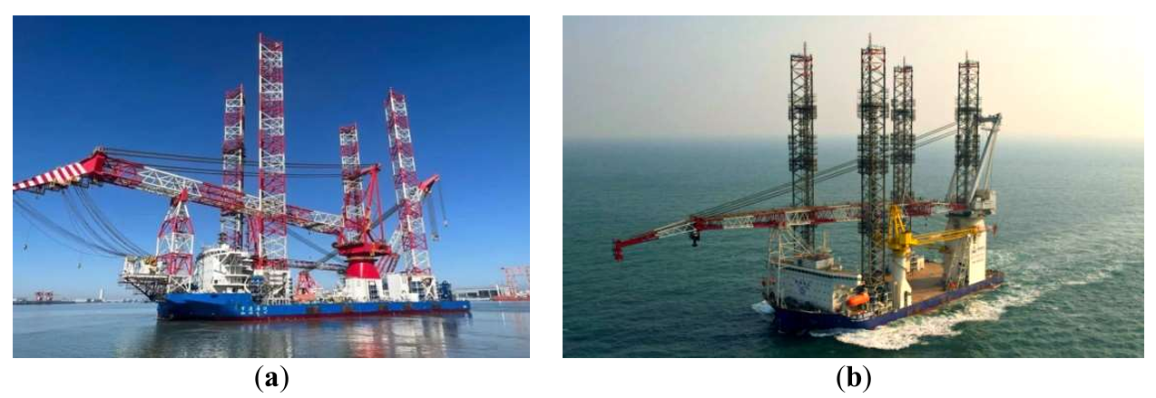
Although China started later in the development and manufacturing of wind turbine installation vessels, it has rapidly advanced with the development of offshore wind power and the support of relevant policies. Chinese shipowners have become an important force in the current offshore wind installation vessel market. According to data, among the top 10 offshore wind installation vessel shipowners globally, six are China shipowners, including Nantong Ocean Water Conservancy Engineering Co., Ltd., Fuzhou, China Communications Haifeng Wind Power Development Co., Ltd., Shanghai Ou Yang Offshore Engineering Group Co., Ltd., and others. Some typical Chinese self-elevating installation vessel models are shown in
and
.
.
Typical self-elevating installation vessels in China.
| Ship Owner |
Ship Name |
Technology Type |
Main Dimensions
/m × m × m |
Main Dimensions/m |
Lifting Capacity/t |
| Tianjin Port and Waterway Engineering |
Port & Navigation Ping 5 |
Jack-up |
135 × 50 × 11 |
135 |
1800 |
| Zhengli Offshore Engineering |
Port & Navigation Ping 5 |
Jack-up |
143.8 × 56.6 × 13 |
136 |
3500 |
| Hengtong Land |
Port & Navigation Ping 5 |
Jack-up |
135 × 50 × 10 |
135 |
1600 |
| CRCC Harbour & Channel engineering bureau |
CRCC Wind Power 2000 |
Jack-up |
136 × 53 × 10 |
131 |
2000 |
| CRCC Harbour & Channel engineering bureau |
CRCC Wind Power 01 |
Jack-up |
105 × 42 × 8.5 |
85 |
1300 |
| Shanghai Zhenhua Heavy Industries |
Longyuan Zhenhua No. 3 |
Jack-up |
100.8 × 43.2 × 8.4 |
85 |
2000 |
| Bridge Bureau |
Bridge Offshore Wind |
Jack-up |
138.3 × 53 × 10 |
131 |
2000 |
| CCCC Third Harbor Engineering Bureau |
Haifeng 1002 |
Jack-up |
133.88 × 50 × 11 |
130 |
1800 |
| Haifeng 1001 |
Jack-up |
133.88 × 50 × 11 |
120 |
2500 |
| Hailong Wind Power |
Hailong Windcai |
Jack-up |
128 × 48 × 9.5 |
130 |
1200 |
| Jujie Technology |
Jujie 1200 |
Jack-up |
110 × 48 × 9 |
120 |
1200 |
| Jujie 1600 |
Jack-up |
123.95 × 48 × 9.5 |
120 |
1600 |
| HaiJian New Energy |
Haijian 020 |
Jack-up |
123.95 × 48 × 9.5 |
120 |
1600 |
| Huaxia Golden Leasing |
Huaxia Honghu |
Jack-up |
106.6 × 44.2 × 8.45 |
120 |
1500 |
| Boqiang Offshore Engineering |
Boqiang 3060 |
Jack-up |
133 × 53 × 11 |
120.5 |
2200 |
| Huaxi Offshore Engineering |
Huaxi Wind 01 |
Jack-up |
136 × 50 × 10 |
125.85 |
1600 |
| China Merchants Group |
China Merchants Chengfeng |
Jack-up |
125 × 48 × 9.5 |
120 |
1600 |
| Three Gorges Corporation |
Baihetan |
Jack-up |
126 × 50 × 10 |
120 |
2000 |
| Ouyang Offshore Engineering |
Ouyang 005/006 |
Jack-up |
90.2 × 43 × 8 |
104 |
800 |
| Ouyang 007/008 |
Jack-up |
90.2 × 43 × 8 |
104 |
800 |
| Baosheng Changfei |
Changsheng 1200 |
Jack-up |
105 × 40.8 × 7.5 |
97.7 |
1200 |
. Jack-up installation vessels in China. (<b>a</b>) Longyuan Zhenhua No. 3; (<b>b</b>) China Railway Construction Corporation CRCC Wind Power 01.
In 2020 and 2021, with the growth in demand for offshore wind power development, orders for crane vessels were steadily delivered, and the fleet’s growth rate rapidly increased. Domestic crane vessels have reached an internationally leading performance level. The lifting capacity of crane vessels used for offshore wind construction has developed from the 1000-ton class to the 12,000-ton class, with lifting heights reaching 130 m. The vessel types have also evolved from catamaran and conventional barge designs to semi-submersible platforms. Notable large crane vessels in China include the Jujie 3600
, Chuangli Hao
, Guansheng Yihang
, and Zhenhua 30
, among others. Typical Chinese floating crane vessels are shown in
and
.
.
Typical floating crane vessels in China.
| Ship Owner |
Ship Name |
Technology Type |
Main Dimensions
/m × m × m |
Lifting Capacity/t |
Lifting Height/m |
| Zhenhua Offshore |
Zhenhua 30 |
Full Rotation |
298 × 58 × 28.8 |
12,000 |
123 |
| CNOOC Engineering |
Blue Whale |
Full Rotation |
217 × 50 × 20.4 |
7500 |
110 |
| Blue Frontier |
Full Rotation |
157.5 × 48 × 12.5 |
3800 |
87 |
| Yantai Salvage Bureau |
Dehe |
Full Rotation |
199 × 47.6 × 15 |
5000 |
97 |
| Jiangsu Huaxi Village |
Huaxi 5000 |
Full Rotation |
178 × 48 × 17 |
5000 |
95 |
| Guansheng Shipping |
Guansheng One hang |
Full Rotation |
168.5 × 51.8 × 11.8 |
2300 × 2 |
125 |
| Shanghai Salvage Bureau |
Chuangli Hao |
Full Rotation |
198.8 × 46.6 × 14.2 |
4500 |
95 |
| Weili Hao |
Full Rotation |
141 × 40 × 12.8 |
3000 |
85 |
| Baosheng Changfei |
Changsheng 5000 |
Full Rotation |
182 × 49 × 15 |
4000 |
116.5 |
| Wenzhou Haobo |
Haobo 4000 |
Full Rotation |
176 × 52 × 12.5 |
4000 |
125 |
| Guangzhou Salvage Bureau |
Huatianlong |
Full Rotation |
174.85 × 48 × 16.5 |
4000 |
95 |
| Yuhang Ocean-Land |
Yuhang Crane 58 |
Full Rotation |
145 × 44.6 × 10.4 |
3800 |
122.8 |
| Yuhang Crane 3000 |
Full Rotation |
148.4 × 44.6 × 12 |
3500 |
103 |
| Yuhang Crane 32 |
Full Rotation |
150.2 × 42 × 10.8 |
3500 |
128 |
| Jujie Technology |
Jujie 3600 |
Full Rotation |
171 × 43.8 × 14.2 |
3600 |
115 |
| Jiangsu Hengtong |
Hengtong 3500 |
Full Rotation |
143 × 55.4 × 10.8 |
3500 |
130 |
| Three Gorges Corporation |
Wudongde |
Full Rotation |
181.65 × 46 × 15 |
3000 |
130 |
| Three Gorges Corporation |
Baihetan |
Full Rotation |
126 × 50 × 10 |
2000 |
160 |
| Nengjian Guanghuo |
Nengjian Guanghuo 002 |
Full Rotation |
181.58 × 48 × 13 |
3000 |
125 |
| Yongjian Ocean |
Yongjian 3000 |
Full Rotation |
171 × 43.8 × 14.2 |
3000 |
115 |
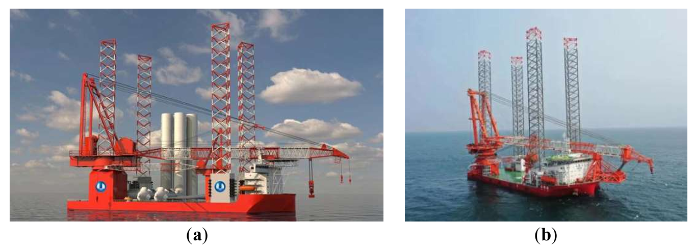
. Offshore wind power installation platform. (<b>a</b>) Wudongde; (<b>b</b>) Baihetan.
Based on the above research results, a maturity mapping of offshore wind power equipment is made using the TRL (Technology Readiness Level) maturity scale from .
Jack-Up Installation Vessel: These are typically at TRL 9, as they are widely used in the offshore wind industry, and the technology is highly mature.
Semi-Submersible Installation Vessel: Likely at TRL 8, as they have been applied in some projects but may still require further testing and validation.
Floating Installation Vessel: These are likely at TRL 6, as they have been validated in laboratory and simulated environments, but they may not yet be mature enough for practical application.
Future development trends in offshore wind power equipment are focused on semi-submersible and floating installation vessels to adapt to deep offshore and large-capacity wind turbine installations.
Conceptualization, X.M. and J.L.; Methodology, H.W.; Software, H.Z.; Validation, X.M., H.Z. and R.L.; Formal Analysis, J.L.; Investigation, H.Z.; Resources, R.L.; Data Curation, R.L.; Writing—Original Draft Preparation, X.M.; Writing—Review & Editing, H.W.; Visualization, J.L.; Supervision, R.L.; Project Administration, J.L.; Funding Acquisition, R.L.
Not applicable.
Not applicable.
All data will be made available upon reasonable request.
This research received no external funding.
The authors declare that they have no known competing financial interests or personal relationships that could have appeared to influence the work reported in this paper.